Portal 2 Puzzle Maker/Logic Gates
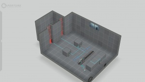
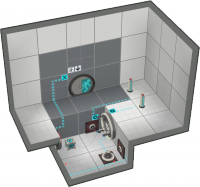
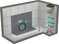
It is possible to make some basic logic gates on the Puzzle maker.
Contents
Video explanation
For a video tutorial on how to make logic gates, click here.
Logic gates
Logic gates are used to merge multiple signals onto a unique one. It has n inputs, like buttons or laser receiver and one output, you can then connect this output to a door, a laser field or something else.
NOT gate
A not gate can be used to reverse a signal. Most of the time you don't need it since you can reverse the signal directly on the output by selecting open by default (for a door) or activated by default.
AND gate
An AND gate is activated when all of its inputs are activated. A good thing for us is that AND gates are implemented by default in the game, you just have to connect all of your inputs to the output.
NAND gate
A NAND gate is the opposite of an AND gate, it is always activated except when all of its inputs are activated. You can do it using lasers or just connect all of your inputs to the output like an AND gate and check activated by default on the output.
OR gate
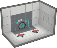
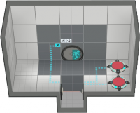
An OR gate is activated when at least one of its inputs is activated. We use laser relay to achieve this. Each input is connected to a laser emitter pointing at the relay, this way you can have up to 5 inputs in a 1x1x1 cube : place the relay on the floor and each laser emitter on the walls and ceiling.
- If there are too many components connected to your relay and you need to connect more just build an other OR gate and connect the relay of the first gate to one of the laser of the second gate.
- Another method is to use a redirection cube (with no dropper) aimed at a laser catcher connected to the desired output. Link your inputs (up to five) to lasers directed at the cube. Should you wish to have more than four inputs, simply add an extra cube to the chain.
NOR gate
A NOR gate is the opposite of an OR gate, it is activated when none of its inputs are activated. You can build one by setting the output of the OR gate to start open (for a door) or start enabled. It can also be created by adding a NOT gate to the output.
XOR gate
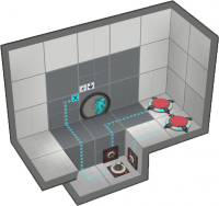
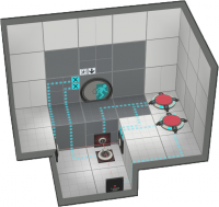
A XOR gate is activated when an odd number of its inputs are activated, most of the time there are only two inputs so the XOR gate is activated when only one of the inputs is activated, or you could say when the inputs are opposite. Again we use lasers to build this gate. We use the equation XOR = (A+B).!(A.B). Just an OR gate and a NAND gate connected to the output are needed. A XOR gate can fit in a 1x1x1 pit.
- XOR gates are particularly useful in adders and related circuits, and can be made in a single 1x1 pit. It can get confusing where your outputs are so it is recommended to use a pit no smaller than 1x2.
- You can build a XOR gate with more than 2 inputs by building multiple XOR gate and connecting the output of each gate to one input of the next gate. The output of the last gate being the final output.
Switch
A switch, while not technically a logic gate, is an important part of setting up the logic gate "system". A switch is a logic item that allows one input to be directed to one of two or more outputs. It consists of:
- 3 laser emitters
- 3 laser catchers
- 2 panels
- a sliding panel (optional)
- a pedestal button to control the sliding panel (optional)
This will give you an input that can be switched between two or more outputs. The outputs can be connected to further logic gates or switches. The outputs can even be used to open the exit door if you want. Whatever you connect the two outputs to will activate when the panel on that side is down.
Latches
Latches are useful to create some sort of memory. This way the game can remember things, for example a button that switches a laser field state every time you press it (the action produced by the button, here : enable or disable the field, depends on the field state which is stored in this memory). You can be very creative in making your own latches, but here are the most compact versions with the fewest entity.
SR latch
An SR latch has two inputs, a SET and a RESET button. When you press the SET button the output is activated, and when you press the RESET button the output is deactivated. If none of the button is pressed the output does not change, it remember its last state. Finally, if both buttons are pressed it's either the SET or the RESET button that wins.
An SR latch can fit in a 1x1x1 cube. An excursion funnel is place in front of a button which is our output (which means it needs to be connected to the door here) and a cube is placed on the floor, so when the funnel is activated the cube will press the button.
The SET and the button are connected to the funnel with an OR gate and change its state (activated or not). So when you press the SET it will activate the funnel and the cube will activate the button. Then the button will keep the funnel activated.
The RESET is directly connected to the funnel and changes its direction. This way, when you press the RESET, the cube is pulled and the funnel stops.
T flip-flop
A T flip-flop is a device that toggles state when the input goes from not activated to activated, this is what happens when you press a button. But when the button is released nothing happens, a T flip-flop is triggered by a rising edge.
The button that toggle the flip-flop is connected to the 3 light bridges, the middle one being activated by default. And the cube dropper is connected to both buttons (this is an AND gate), this way when the toggle button is pushed AND the cube is on the button, the cube is fizzled and a new one is dropped onto the bridges. The last bridge prevents the cube from touching the button while the toggle button is activated
The output is the button (the cube activates it every other time) so it needs to be connected to the door here.
Delayers
Basic Delayers
Basic delayers or uncontrollable delayers are created by placing an excursion funnel with a box button at the end of it. Place a box dropper above the excursion funnel, make sure that "auto drop first cube" and "auto respawn cube" are disabled. The length of the delay is changed by how far away the box dropper is from the button.
Advanced Delayers
Advanced delayers or controllable delayers are very complex. First create four raised blocks on one side place two laser catchers and on the other two laser emitters. Place a button, the one that you want to start the delay, and connected it to the first laser. The laser catcher that faces the first laser should be connected to the second laser emitter. The second laser emitter should be set to on by default, so that when the laser gets powered it turns off, this creates a NOT gate. Now create a basic latch (non-resetable) and connect the input to the button you are using at the start of the delay. The output should be connected to a basic delayer, as detailed above, the delayer should have a one block space between the button and the dropper. Next create the item you want to use as you output and connect the box button from the basic delayer to it and also connect the second laser catcher. To control the length of the delay change the button "on" time.
Tips
- If you don't want your logic gates to be visible when playing the map, you can place them in a completely-isolated, inaccessible "room" outside of the level.
- Only do this if the connection will remain clear. It is often better to place logic gates within view behind glass than to completely hide them from the player.
- Using this method will usually result in marker symbols being placed next to items to show connections. Since in these cases the connected object will not be visible, you can prevent players from unnecessarily searching for it by setting "Connection Visibility" to "None" for the relevant items.
| ||||||||||||||||||||||||||||||

