Displacement
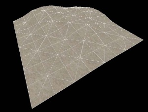
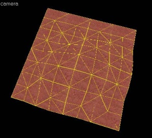
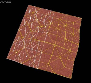
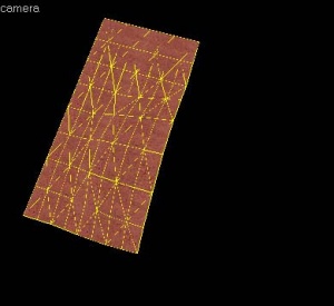
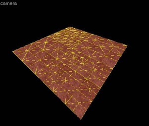
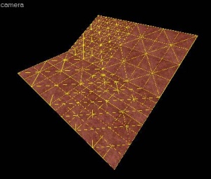
Displacements are quadrilateral (4-sided) brush surfaces that have been converted to a mesh of triangular polygons which can be freely distorted and sculpted into various shapes. Displacements in the ![]() Source engine are typically used to create terrain such as hills, valleys, trenches, slopes, etc, but can sometimes be used as flat surfaces to blend between two or more textures.
Source engine are typically used to create terrain such as hills, valleys, trenches, slopes, etc, but can sometimes be used as flat surfaces to blend between two or more textures.
- Power of 4 displacements can cause crashes if colliding with physics objects (except in
 ).
). - In

 , if "Batch displacement rendering" is checked in Hammer's general options, manipulating displacements in any way could cause Hammer to crash without reason.
 - Displacements can be badly lightmapped (totally black), there are several reasons for that:
- A bad landing area in a room which you use for sky_camera
 Example:You have a mix of displacements and brush boxes, it can cause your main gameplay area with displacements to turn to black, select only one type and check it for errors!
 - Only displacement edges, caused by undeleted faces from the back side of your displacement brush
 Fix:Select the whole displacement brush and deselect only the face which will be seen to the player, then click displacement->destroy.
 - You compiled your map with VRAD fast (not normal or final)
- A bad landing area in a room which you use for sky_camera
- Sometimes complex displacements are flickering no matter what you do.
 Fix:You can split them into several parts and remove the part outside or deep inside brush geometry.
 Fix:Select a glitching one, use "Move selected to entity" and then "to World" and save of course, this helps, especially when the map was built with a different hammer version. Always check that you sewed them properly and you have no gaps between them.
Benefits
- They are rendered in batches, making it very cheap: per polygon face actually cheaper than standard brush geometry!
- They can be altered using the Paint Geometry tool to sculpt a wide variety of shapes, well beyond what can be created with brushes.
- An alpha channel for can be painted per-vertex to blend between two textures on the displacement. This can be used to create transitions between dirt and rock, for example.
- Can be automatically populated with detail props.
Limitations
- They must always be four-sided (see below for a messy workaround).
- They must always be static, and never attached to an entity, meaning you cannot set displacements as brush entities, such as func_breakable, func_detail, or func_brush. Doing so will usually result in an error message from VBSP before halting the compile process.
- They do not block visibility and do not seal the map from leaks.
- A single map is limited to a total of 2048 displacements in
 games. In
  this limit is at 4096. In
  this limit is at 16384. In
  this limit is at 32768.
 - The bigger the displacement is, the less you will be able to lower the lightmap under a certain value.
- Power of 4 displacements are not compressed under the normal compile tools (patched compile tools overcome this), and are prone to physics bugs and crashes.
Other characteristics
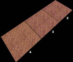
- There are three levels of resolution (higher resolution means more tris), but ultimately the maximum visual detail is determined by the size of the displacement. Cut one up if more detail is needed.
- Direct light is blocked on both sides, but bounced light is not blocked by the invisible backface.
- A single brush can host as many displacements as it has faces (the brush itself is not compiled).
Displacement editing shortcuts
- Alt+right click
- When the axis in paint geometry is set to face normal, will set the axis to the direction perpendicular to the face you clicked on.
- Shift
- Ignores the distance setting, allowing sections to be dragged freely.
- Right click
- Reverses the direction of the paint geometry tool.
Construction
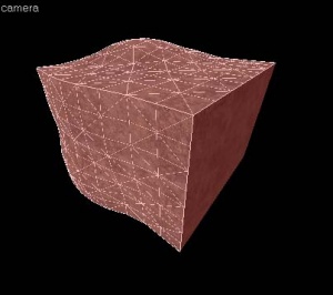
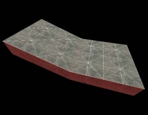
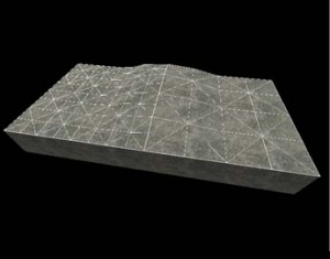
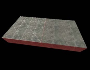
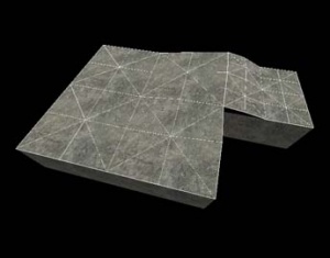
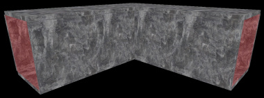
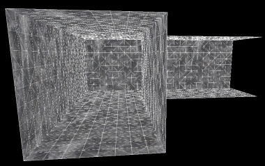
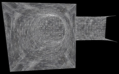
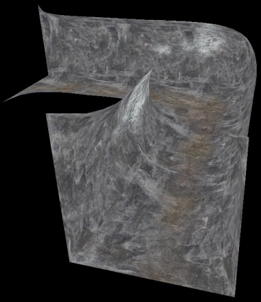
Displacements are created by using one of the faces on a brush solid as a base face. Once the displacement surface has been created, the brush face used as the base face is discarded when the map is compiled. Additionally, if a brush solid contains any displacement surfaces, all of the non-displacement sides are discarded when the map is compiled and run in the engine. In other words, once you convert a brush solid to include displacements, the brush solid is no longer a solid object and is removed when you run the map.
The following images illustrate this characteristic:
Basic displacement creation
How to create and paint a displacement surface:
- Create a brush with the Block Tool that will be used as the base for the created displacement surface.
- Click the Texture Application tool to bring up the Face Edit dialog, and select the Displacement tab.
- In the 3D view, left-click on a brush face to select it. Ctrl-click to add or remove faces from the current selection.
- Click Create in the Displacement tab. Enter a value from 2 to 4 for the displacement density and click OK.
 Warning:Power 4 displacements are usually advised against since they might cause errors. Power 4 displacements might work better in newer engine versions.
 Note:You can change a displacement's power later in the "attributes" section, but be warned that the higher detail from the displacement being its power is permanently lost when lowering the power.
 - Select the Paint Geometry tool on the Displacement tab. The Paint Geometry panel will open.
- In the 3D View, Left-click on a displacement to raise a section, and right-click to lower it. Use the Radius slider in the Paint Geometry panel to control the size of the painting sphere.
See Paint Geometry for more information on displacement painting.
Displacement options
![]() Use the Displacement Mask button on the Map Operations toolbar to toggle the display and selection of the non-displacement sides of brush.
Use the Displacement Mask button on the Map Operations toolbar to toggle the display and selection of the non-displacement sides of brush.
You can also have more than one displacement surface for each brush, like the image on the left. As long as a brush side has 4 edges, you can make a displacement surface out of it.
See Face Edit, Displacements for a description of all the ways you can paint the geometry on a displacement.
Sewing displacements
The Sew button on the Displacement tab can be used to connect the edges of two or more selected displacement surfaces. To sew two or more displacements, select the displacement faces that should be sewn together and press the Sew button.
You can sew displacement surfaces in any of the following circumstances:
- Any two displacements whose base face brush surfaces share a common edge with coincident endpoints.
- A displacement surface to a non-displacement brush face, if the base face of the two share a common edge with coincident endpoints.
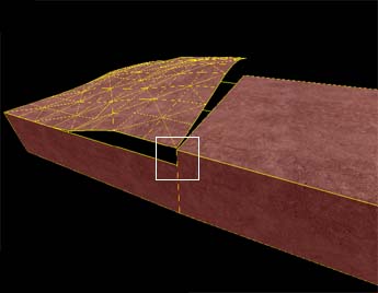
- A displacement surface to another displacement surface where a shared edge is exactly half the width of the other (called a T-junction).
You can sew displacements with different resolution settings — the vertices of the higher resolution displacement will be moved to match the vertices of the lower resolution displacement.
Examples of circumstances where the Sew command can be used:
Surfaces cannot be sewn together if the base faces of the displacements do not share a common edge:
Surfaces also cannot be sewn together if they don't share a common "Elev"ation attribute, which is found along side the Power and Scale attributes.
Subdividing displacements
The Subdivide button on the Displacement tab can be used to smooth two or more selected displacement surfaces in relation to their position. To subdivide two or more displacements, select the displacement faces that should be subdivided and press the Subdivide button. If the subdivision is not successful, you'll see areas where displacement faces appear Buggy and out of place. In order for a subdivision to be successful, the vertices of the selected displacements must align perfectly.
Other methods of altering displacement geometry
Besides the displacement painting tools, some of the standard brush manipulation tools work on displacement surfaces. It works well to control the contours of the displacement with the paint tools, and do larger manipulations with the following tools.
Transformations
![]() Displacements can be freely moved, scaled, rotated and sheared with the Selection Tool, just like standard brushes. The transformation is done to the base brush face, and the displacement follows.
Displacements can be freely moved, scaled, rotated and sheared with the Selection Tool, just like standard brushes. The transformation is done to the base brush face, and the displacement follows.
Clipping
![]() The Clip Tool can also be used to clip displacement surfaces. This can be used to trim off unneeded sections of the displacement surface, or to divide a displacement into two pieces without changing its shape.
The Clip Tool can also be used to clip displacement surfaces. This can be used to trim off unneeded sections of the displacement surface, or to divide a displacement into two pieces without changing its shape.
The following example shows how the Clip Tool can be used to trim a displacement surface:
Vertex manipulation (Technique)
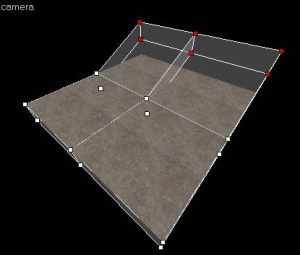
![]() The Vertex Tool can also be used to clip displacement surfaces. Vertex editing works well to shift the corners of the displacement to meet important edges, or to raise whole section of terrain without having to paint it by hand when creating hills or elevated surfaces.
The Vertex Tool can also be used to clip displacement surfaces. Vertex editing works well to shift the corners of the displacement to meet important edges, or to raise whole section of terrain without having to paint it by hand when creating hills or elevated surfaces.
There are some important restrictions when vertex editing displacements:
- Vertex editing is done on the base face, not the displacement itself.
- Collapsing or adding vertices is not allowed, and will destroy displacements attached to the base faces; the end result must be a quadrilateral.
- The end result of the vertex editing must be a planar surface. Making a non-planar surface will destroy attached displacements.
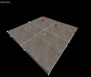
The following example shows how the Vertex Tool can be used to raise a section of displacements:
Creating holes in displacements
Sometimes you need to create a hole or gap in displacement surfaces for various reasons. See Creating Holes in Displacements for information on how to create holes in displacement geometry.
Blended displacement materials (vertex alpha painting)
The Paint Alpha tools allow you to blend between two different textures on a displacement surface by painting the alpha values of each vertex. The alpha value dictates data about the transparency of the two textures assigned to the surface. This can be used to create transitions in the texturing, like grass to dirt, sand to rock, etc. To do vertex alpha material blending, special blend materials are made specifically for this purpose that contain the necessary shader. Only these materials can be used for blending. If one of the standard (non-blended) materials are used, the Paint Alpha tools will have no visible effect.
To add a blended material to a displacement surface and paint the vertex alpha data to blend the textures:
- Choose the Texture Application Tool to open the Face Edit dialog box.
- Left-Click in the 3D View to select a displacement face you wish to add a blend material to.
- Click the Browse button on the Material tab of the Face Edit dialog box.
- When the Texture Browser appears, type
blendinto the filter field at the bottom of the Texture Browser. - Double-left-click to select one of the blended materials and close the Texture Browser.
- Click the Apply button on the Face Edit dialog to apply the material to the displacement surface.
- Click the Displacement tab on the Face Edit dialog.
- Click the Paint Alpha button on the Displacement tab to open the Paint Alpha tools.
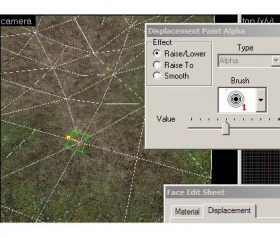
- Click the Value slider field, and type a value between 30-100 as a starting point. Make sure that Raise/Lower is selected under Effect. Lower numbers in the Value field paint the vertex alpha data at a slower pace, higher numbers paint the data faster.
- Left-click on one of the vertices of the displacement in the 3D View to add vertex alpha data. Right-click on the displacement to remove data.
See Paint Alpha for more information on the alpha painting tools.
Triangular displacements
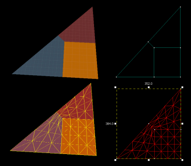
Sometimes it is necessary to have a displacement surface which has only three sides. Since displacements can only be created from quads, this requires creating a triangle out of three separate quads, as displayed to the right.
See also
External links
- Practical Cliffs (interlopers.net)
- Wall Worm Displacement Tools - Creating displacements inside 3ds Max
- Displacement vs func_detail: A comparative FPS study - analysis comparing displacements and func_detail
| Environment articles: | |
|---|---|
| Skies and environment maps | |
| Terrain and displacement mapping | Displacements • Creating Holes in Displacements • Digital Elevation Models • Creating custom terrain with Worldmachine |
