Creating Holes in Displacements
Sometimes you need to create a hole or gap in displacement surfaces for various reasons. Due to the requirements of displacements, there is no automatic way to accomplish this. Instead, you can use a combination of vertex editing and clipping to achieve the result. Using these methods, you can create holes in displacement surfaces that share common edges, which allows them to be painted, sewn and transformed as one surface.
The method you choose depends on whether you're starting from scratch, or if a displacement already exists where you need a hole.
Difference between the two methods
- More accurate geometry;
- More accurate blend;
- Cleaner lightmapping (not shown in the screenshot below).

Creating a New Set of Displacement Surfaces With a Hole
The best method to create holes in displacement surfaces is to create the hole when the displacements are first created.
Follow these steps to create a set of displacements with a square hole in the center:
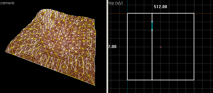
- Create a new brush with the Block Tool. The brush should be the size of the displacement you wish to create:
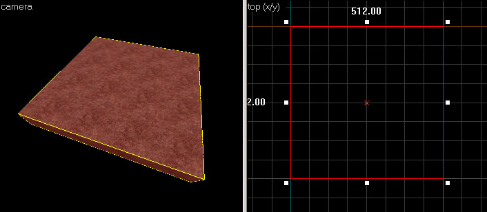 Create a brush the size of the displacement.
 - Use the Clip Tool in the Top 2D View to cut the brush in the vertical direction. This split will be the left side of the hole:
 Note:Press the Clip Tool icon until both sides of the brush are highlighted in white.
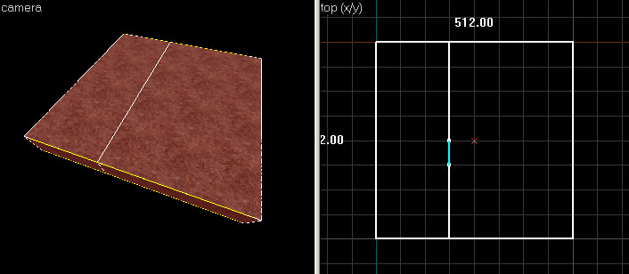 Using the Clip Tool to create the left side of the hole.
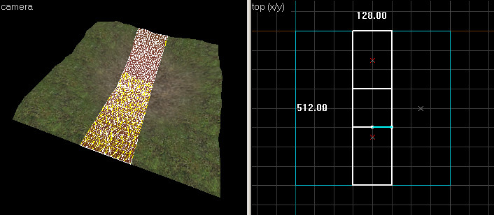
 - Use the Clip Tool to cut the brush three more times -- cut the brush on the right side first.
Then select the center piece with the Selection Tool.
Switch back to the Clip Tool and clip the center brush two times horizontally, to create a square in the middle. The end result should look something like this: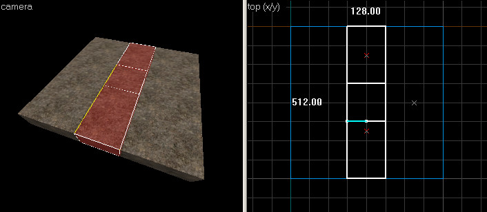 Cut the brush for the other sides of the hole.
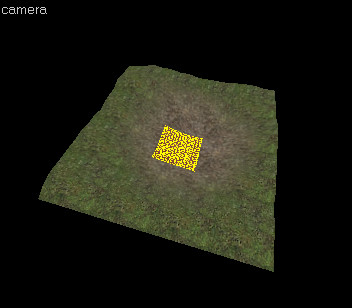
 - Using the Selection Tool, select the brush square in the middle that was a result of the clips you made. Press the Delete key to delete the brush, leaving a hole in the center of the brushes:
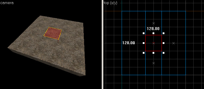 Select the center brush and delete it.
 - Select the two side brushes with the Selection Tool:
 Select the side brushes.
 - Select the Vertex Edit Tool to go into Vertex Editing Mode:
 Switch to Vertex Editing Mode.
 - In the Top 2D View, select the corner point, and drag it towards the center square, as shown:
 Move a corner point towards the corner of the hole.
 - Repeat the same operation for the other three corners -- drag them toward the four center points as shown:
 Move the other corner points to match.
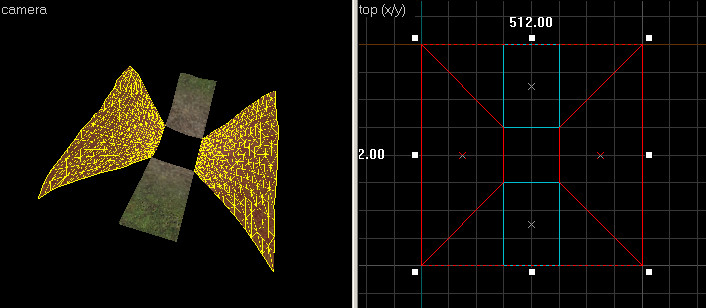
 - While still in Vertex Edit Mode, select one of the remaining two brushes. Hold down Ctrl and select the other one as well. Your selection should match this image:
 Select the other two brushes using CTRL-left-click.
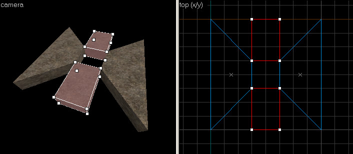
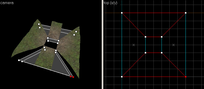
 - Drag the outer vertices of these brushes to line up with the four outer corners, to match the following image:
 Vertex edit the brushes to fit the outer edges.
 - Switch to the Texture Application Tool, and select all of the top faces of the brushes by left-clicking one of them in the 3D View, then holding down CTRL and left-clicking the remaining faces. Only select the tops of the brushes, as shown here:
 Select all the top faces in Face Edit Mode.
 - Switch to the Displacement tab in the Face Edit dialog box. Press the Create button to create the displacements on the selection faces. You should now have a set of displacements with a hole cut in the center:These displacements can now be freely painted or transformed. Because the four outside edges are not split, these displacements can be sewn to and surrounding geometry seamlessly.
 Create the displacements using the brushes you've edited.


Using Clipping to Add Holes to Existing Displacements
Creating a hole where you have already have displacements is done utilizing the clip tool in combination with vertex editing. This method is not as straightforward as making a hole by creating new displacements, but it will preserve some of the shape of any existing surfaces.
Follow these steps to make a hole in the center of an existing displacement surface:
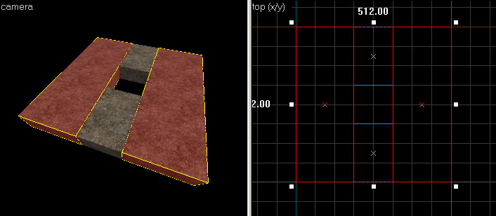
- Select the displacement you wish to create a hole in with the Selection Tool:
 The target displacement.
 - Use the Clip Tool to cut the displacement in the vertical direction. This split will be the left side of the hole:
 Using the Clip Tool to create the left side of the hole.
 - Use the Clip Tool to cut the brush three more times -- Cut the displacement on the right side, as well as two times horizontally, to create a square in the middle:
 Cut the brush for the other sides of the hole.
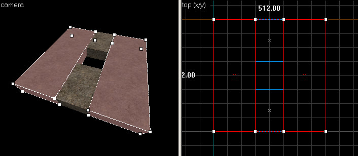
 - Using the Selection Tool, select the displacement square in the middle that was a result of the clips you made. Press the Delete key to delete the displacement, leaving a hole in the center:
 Select the center brush and delete it.
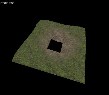 The center displacement has been deleted, leaving a hole.
 - We're not finished yet, because the displacement still needs to be fixed up so it can Sew properly to neighboring surfaces.Switch to the Clip Tool and select the displacement on the right side. In the Top 2D View, use the Clip Tool to trim off the corner piece of the displacement.
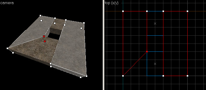
Make sure the clip snaps to corners on the grid, or the displacement will get destroyed: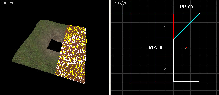 Use the Clip Tool to trim the displacement towards the hole.
 - Repeat the same operation for the other corner of the displacement, as well as the displacement on the left side -- clip each of the corners to create the edges as shown:
 Clip the the edges on the left and right side.
 - Switch to the Vertex Edit Tool. Select one of the remaining two top and bottom displacements. Hold down CTRL and select the other one as well. Your selection should match this image:
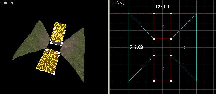 Select the other two displacements using Ctrl+left click.
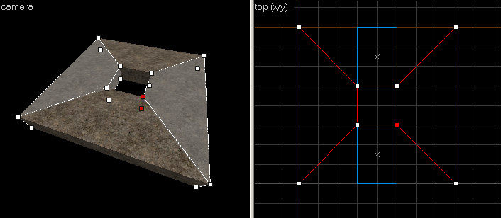
 - Drag the outer vertices of these two displacements to line up with the four outer corners, to match the following image:
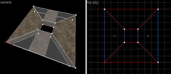
 Vertex edit the displacements to fit the outer edges.
 - Switch to the Face Edit Tool, click the Displacement tab of the Face Edit dialog. Select all of the displacement surfaces by left-clicking one of them in the 3D View, then holding down CTRL and left-clicking the remaining faces. Only select the four displacements.
Notice how the displacements edges do not line up, due to the clipping that was done: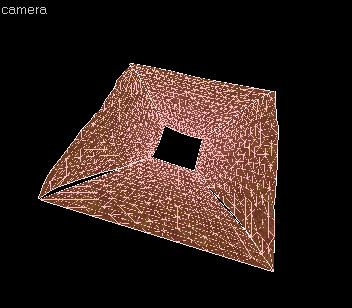 Select all the displacements in Face Edit Mode.
 - Click the Sew button. The displacements should connect to each other like this:
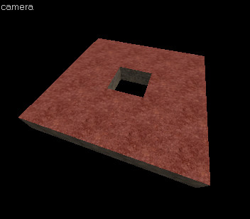
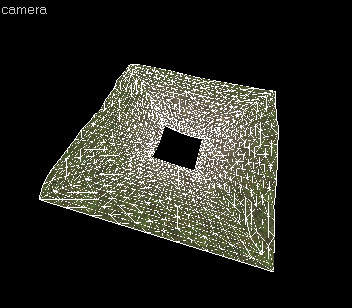 The final displacements with a hole, after the Sew operation.


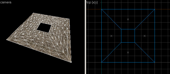
These displacements can now be freely painted or transformed. Because the four outside edges are not split, these displacements can be sewn to and surrounding geometry seamlessly.
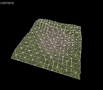
The following images demonstrate how the displacement geometry created in the previous steps can be attached to other displacements:


See also
| Environment articles: | |
|---|---|
| Skies and environment maps | |
| Terrain and displacement mapping | Displacements • Creating Holes in Displacements • Digital Elevation Models • Creating custom terrain with Worldmachine |