Creating Your First Room
Introduction
This guide was created for newer users and returning Source engine users to get started with, and transition into using the new methods of map creation in ![]() Source 2's Hammer Editor using the Source 2 tools.
Source 2's Hammer Editor using the Source 2 tools.
A lot of returning map makers from the Source Engine may find themselves used to creating maps out of individual brushes, however since Source 2 now entirely uses mesh based map making; this older style of brush based mapping will cause lighting artifacts, lighting leaks, and unecessary faces being rendered - eventually causing potential performance issues down the road.
If you are previously already familiar with mesh based modeling from 3D software such as Blender, you will have an easier time moving to Source 2's method of map making.
You will be assumed to already be familiar with the Hammer Overview, and that you have read and understand the Basic Construction articles on mesh editing.
Requirements
A list of point entities used during this guide follows:
- info_player_start
- light_omni
 Note:Use light_omni2 instead for
  .
.
Creating your First Room
Creating the Mesh
- Go to File → New Ctrl+N to create a new map file.
- Select the Block Tool. ⇧ Shift + B
- Select Block under Geometry Type from the Tool Properties pane if it already isn't selected.
- In your preferred choice of viewport:
 Click and drag along the workplane grid until until you have a square block of 256 units in width and length, and let go of the mouse button to create a block mesh.
  Click and hold the mouse button on the blue handle, in the center of the top face of the mesh, and drag to resize the mesh vertically up to 128 units - press ↵ Enter when you are finished resizing the mesh.
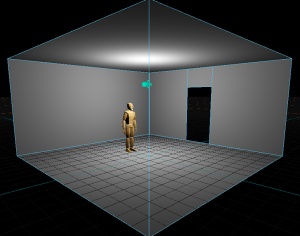
- Now press F to invert the mesh faces - you now have a room with four walls, a floor and a ceiling with an adequate room height for moving around in.
Placing the Player Spawn Point
- Select the Entity Tool. ⇧ Shift + E
- Search for info_player_start in the Entity Class dropdown list in the Tool Properties pane by typing into the field - or click Player Start in the Player category section below it.
- In the 3D viewport:
 Click anywhere on the floor to place a spawn point for the player. This determines where the player will start from when your map loads in-game, it should not intersect with any walls or objects.
Adding Lighting to your Room
- Now we need some lighting, while keeping the Entity Tool selected, search and select light_omni from the Entity Class list - or click Point Light in the Lighting category section.
- In the 3D viewport
 Click anywhere to place the light_omni entity - this is a light entity that emits light from a single point in all directions, similar to a lightbulb.
 - Press T to enter the Translate tool
 Click and drag one of the colored arrows to move the light to a good spot, such as slightly below the center of the ceiling. Moving it too close to the ceiling may cause unrealistic looking blobs of lighting, this is up to you to decide where to place your lights.
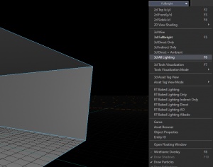
- In the 3D viewport, expand the top right shader dropdown list and select 3d All Lighting F6 to preview your lights in-editor.
Adding a Doorway
Clipping Tool
There are two methods of cutting through meshes and creating holes, the first method is to use the Clipping tool which many will be familiar with from the Source Engine's Hammer Editor. This still works in the same way, and you may choose which side of the cut line to keep.
- Go into Face selection mode by selecting Faces at the top toolbar - or press 3
 Click and select the face you want to cut a hole through.
- Select the Cut Tool ⇧ Shift+X
- In your viewport of choice,
 Click and drag to draw a line that determines where the cut will be placed - place your first cut vertically along one of the walls of the room. You can move each of the cyan colored vertices by clicking and dragging them if you need to re-adjust them - if you need finer control over the placement, you can lower the grid size as the vertices will snap to the grid by default.
 - In the Tool Properties pane, select to Keep Both sides of the mesh that you cut through. Press ↵ Enter to confirm the cut.
- Place a second cut about 48 units away from the first cut.
- Now select the face inbetween the two cuts, and place a third cut horizontally across the face, about 96 units above the floor.
- Select the leftover face below your third cut, and press Delete to delete it, and you will have a hole for a doorway. This is where you would normally place a doorframe model and some type of door entity.
Cut Tool
The second method is to use the Cut Tool, this tool works similar to knife cutting techniques in 3D modeling software, where you first click to set a starting vertex point, and then click somewhere else to set an end vertex point for the cut, with any number of extra points inbetween. This method effectively lets you trace out the cut on the mesh face you are working with, with multiple vertex points for corners or turns. These snap to the grid by default.
- Go into Face selection mode by selecting Faces at the top toolbar - or press 3
 Click and select the face you want to cut a hole through.
- Enter cutting mode C - if you hover the mouse over the selected face you will notice a yellow vertex point with a yellow line extending from it - this is a preview of where the cut will be made. These points must always begin from the edge of a face, and must preferably end at an edge to ensure the face does not become an invalid n-gon.
- In the 3D viewport,
 Click to set the first cutting point towards the center of the wall, on the edge that joins with the floor.
 - Now move the mouse straight up vertically, until you reach the edge that joins the ceiling. Ensure the edge turns green, and
 Click on the edge to set an end point for the cut.
 - Press ↵ Enter to confirm the cut.
- Place a second cut about 48 units away from the first cut, from the floor to the top.
- Now select the face inbetween the two cuts, and place a third cut horizontally across the face, about 96 units above the floor.
- Select the leftover face below your third cut, and press Delete to delete it.
Additional
Notes
- Press Q while in Mesh selection mode if you need to re-enter the mesh resizing tool.
- Turning off grid snapping is not recommended for the cutting tools, as it will be near impossible to create perfectly straight and uniform cuts.
- In-editor lighting will never 100% accurately depict lighting as it appears in-game, as it only previews direct lighting and not indirect light bounces. If your lights are significantly brighter in-game than they appear in the editor, set Tonemap Scale to Auto in the top right toolbar to get the in-editor lighting preview as accurate as possible.
- As a general note, Source 2 maps are no longer required to be sealed off to the void to prevent leaks, however it will still be beneficial to do so to help the VIS calculation processes during compile.
- Likewise, the toolsnodraw material is no longer needed on surfaces the player will never see in-game, as you can now simply just select the face and delete it entirely.
Next: Prefabs and Instances

