Ru/Displacement
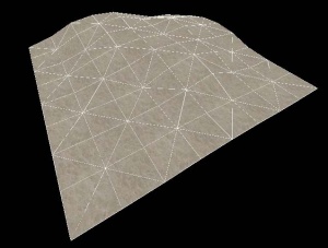
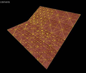
Деформация - это поверхность браша, преобразованная в сетку из полигонов, которую можно свободно искажать и придавать ей различные скульптурные формы. Деформация необходима для создания участков земли: холмов, долин, канав, склонов и т.д.
Преимущества
- При визуализации в пачках сильно облегчают нагрузку: поверхность полигона значительно легче стандартного геометрического браша!
- С помощью инструмента Paint Geometry могут приобретать разнообразную форму, какую только можно создать из брашей.
- Альфа канал может окрашивать вертексы, чтобы смешивать две разных текстуры на деформации. Например, это можно использовать для создания перехода между грязью и камнями.
- Может автоматически заполняться проп деталями.
Ограничения
- Всегда должны иметь четыре стороны.
- Всегда должны быть статичны и не иметь отношения к сущностям, то есть не преобразовываться в брашевые сущности, такие как func_breakable и func_brush.
- Не закрывают утечки на карте.
- Один уровень ограничен в общей сложности 2032 деформациями power 3.
Другие характеристики
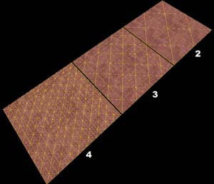
- Существует три уровня разрешения, но в конечном итоге количество полигонов определяется размерами деформации. Если нужно подробнее, вырежьте один (Ctrl+X).
- Своей противоположной стороной не блокируют свет.
- Поверхности браша могут быть деформированы как угодно (сам браш не компилируется).
Известные проблемы
- Будьте осторожны, используя в деформации power 4. Физика столкновений с power 4 иногда вызывает серьезную ошибку.
Общий принцип
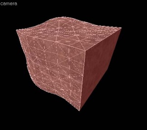
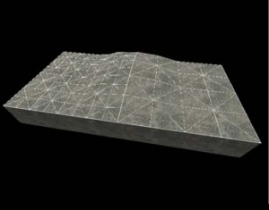
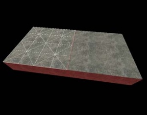
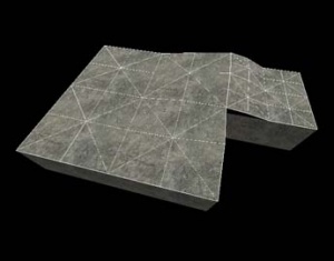
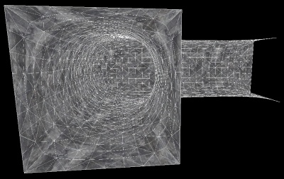
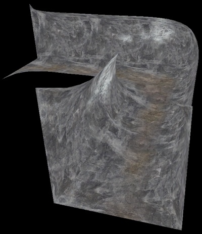
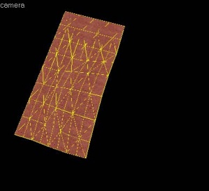
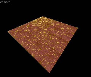
Деформация создается на одной стороне браша, которая называется базовой гранью. После образования деформированной поверхности, базовая грань отбрасывается во время компиляции карты. Кроме того, если твердый браш содержит другие деформированные поверхности, все не-деформированные стороны будут отброшены после того, как карта будет скомпилирована и запущена в движке. Другими словами, после преобразования твердого браша в деформацию, он перестает быть твердым телом и удаляется во время запуска карты.
Следующие картинки иллюстрируют эти особенности:
Основы создания деформации
Как создать и расписать поверхность деформации:
- С помощью инструмента Block нарисуйте браш, который будет использован для создания деформированной поверхности.
- Щелкните по инструменту Texture Application, чтобы вызвать диалог Face Edit, и выберите закладку Displacement.
- В окне 3D, щелкните левой кнопкой по грани браша, чтобы выделить ее. Удерживайте Ctrl, чтобы добавлять или убирать соседние грани.
- В закладке Displacement щелкните Create. Введите значение плотности деформации от 2 до 4 и нажмите OK.
- В закладке Displacement выберите инструмент Paint Geometry. Откроется панель Paint Geometry.
- В окне 3D, левой кнопкой поднимайте выбранную деформацию, а правой опускайте ее. Используйте ползунок Radius на панели Paint Geometry, чтобы изменять размер рисующей сферы.
Дополнительную информацию по рисованию деформации см. в Paint Geometry.
Displacement options
![]() Use the Displacement Mask button on the Map Operations toolbar to toggle the display and selection of the non-displacement sides of brush.
Use the Displacement Mask button on the Map Operations toolbar to toggle the display and selection of the non-displacement sides of brush.
You can also have more than one displacement surface for each brush, like the image on the left. As long as a brush side has 4 edges, you can make a displacement surface out of it.
See Face Edit, Displacements for a description of all the ways you can paint the geometry on a displacement.
Sewing displacements
The Sew button on the Displacement tab can be used to connect the edges of two or more selected displacement surfaces. To sew two or more displacements, select the displacement faces that should be sewn together and press the Sew button.
You can sew displacement surfaces in any of the following circumstances:
- Any two displacements whose base face brush surfaces share a common edge with coincident endpoints.
- A displacement surface to a non-displacement brush face, if the base face of the two share a common edge with coincident endpoints.
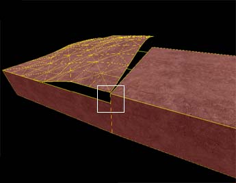
- A displacement surface to another displacement surface where a shared edge is exactly half the width of the other (called a T-junction).
You can sew displacements with different resolution settings — the vertices of the higher resolution displacement will be moved to match the vertices of the lower resolution displacement.
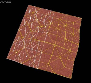
Examples of circumstances where the Sew command can be used:
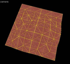
Surfaces cannot be sewn together if the base faces of the displacements do not share a common edge:
Surfaces also cannot be sewn together if they don't share a common "Elev"ation attribute, which is found along side the Power and Scale attributes.
Subdividing displacements
The Subdivide button on the Displacement tab can be used to smooth two or more selected displacement surfaces in relation to their position. To subdivide two or more displacements, select the displacement faces that should be subdivided and press the Subdivide button. If the subdivision is not successful, you'll see areas where displacement faces appear buggy and out of place.
Other methods of altering displacement geometry
Besides the displacement painting tools, some of the standard brush manipulation tools work on displacement surfaces. It works well to control the contours of the displacement with the paint tools, and do larger manipulations with the following tools.
Transformations
![]() Displacements can be freely moved, scaled, rotated and sheared with the Selection Tool, just like standard brushes. The transformation is done to the base brush face, and the displacement follows.
Displacements can be freely moved, scaled, rotated and sheared with the Selection Tool, just like standard brushes. The transformation is done to the base brush face, and the displacement follows.
Clipping
![]() The Clip Tool can also be used to clip displacement surfaces. This can be used to trim off unneeded sections of the displacement surface, or to divide a displacement into two pieces without changing its shape.
The Clip Tool can also be used to clip displacement surfaces. This can be used to trim off unneeded sections of the displacement surface, or to divide a displacement into two pieces without changing its shape.
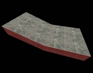
The following example shows how the Clip Tool can be used to trim a displacement surface:
Vertex manipulation (Technique)
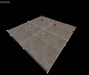
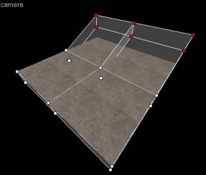
![]() The Vertex Tool can also be used to clip displacement surfaces. Vertex editing works well to shift the corners of the displacement to meet important edges, or to raise whole section of terrain without having to paint it by hand when creating hills or elevated surfaces.
The Vertex Tool can also be used to clip displacement surfaces. Vertex editing works well to shift the corners of the displacement to meet important edges, or to raise whole section of terrain without having to paint it by hand when creating hills or elevated surfaces.
There are some important restrictions when vertex editing displacements:
- Vertex editing is done on the base face, not the displacement itself.
- Collapsing or adding vertices is not allowed, and will destroy displacements attached to the base faces.
- The end result of the vertex editing must be a planar surface. Making a non-planar surface will destroy attached displacements.
The following example shows how the Vertex Tool can be used to raise a section of displacements:
Creating holes in displacements
Sometimes you need to create a hole or gap in displacement surfaces for various reasons. See Creating Holes in Displacements for information on how to create holes in displacement geometry.
Blended displacement materials (alpha channel painting)
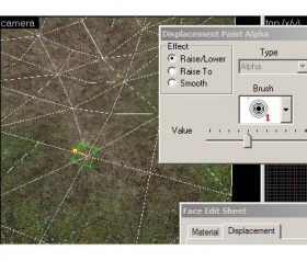
The Paint Alpha tools allow you to blend between two different textures on a displacement surface by painting the alpha channel. The alpha channel contains data about the transparency of the two textures assigned to the surface. This can be used to create transitions in the texturing, like grass to dirt, sand to rock, etc. To do alpha channel material blending, special blend materials are made specifically for this purpose that contain the necessary shader. Only these materials can be used for blending. If one of the standard (non-blended) materials are used, the Paint Alpha tools will have no visible effect.
To add a blended material to a displacement surface and paint the alpha channel data to blend the textures:
- Choose the Texture Application Tool to open the Face Edit dialog box.
- Left-Click in the 3D View to select a displacement face you wish to add a blend material to.
- Click the Browse button on the Material tab of the Face Edit dialog box.
- When the Texture Browser appears, type
blendinto the filter field at the bottom of the Texture Browser. - Double-left-click to select one of the blended materials and close the Texture Browser.
- Click the Apply button on the Face Edit dialog to apply the material to the displacement surface.
- Click the Displacement tab on the Face Edit dialog.
- Click the Paint Alpha button on the Displacement tab to open the Paint Alpha tools.
- Type 100 into the Value slider field. Make sure that Raise/Lower is selected under Effect. Lower numbers in the Value field paint the alpha channel data at a slower pace, higher numbers paint the data faster.
- Left-click on one of the vertices of the displacement in the 3D View to add alpha channel data. Right-click on the displacement to remove data.
See Paint Alpha for more information on the alpha painting tools.
Displacement editing shortcuts
- Alt+right click
- When the axis in paint geometry is set to face normal, will set the axis to the direction perpendicular to the face you clicked on.
- Shift
- Ignores the distance setting, allowing sections to be dragged freely.
- Right click
- Reverses the direction of the paint geometry tool.
See also
External links
- Practical Cliffs (interlopers.net)
- Wall Worm Displacement Tools - Creating displacements inside 3ds Max
| Статьи об окружающей среде | |
|---|---|
| Текстуры неба и создание неба | |
| Создание рельефа местности и деформация поверхностей | Деформированные поверхности • Создание отверстий в деформированных поверхностях • Цифровые модели местности • Создание рельефа в Worldmachine |
