Ru/Creating Holes in Displacements
Template:Otherlang2 Иногда, по каким-либо причинам, вам необходимо создать дырку или проем в деформированных поверхностях. Из-за требований к деформациям, автоматически это сделать нельзя. Вместо этого вы можете использовать комбинацию из вертексного и обрезного редактирования. С их помощью вам удастся создать дырки в деформированных поверхностях с совмещенными гранями, а затем рисовать, сшивать и трансформировать их как одну поверхность
Способ зависит от того, начинаете ли вы с нуля, или у вас уже есть деформация, где нужна дырка.
Создание новых деформированных поверхностей с дырками
Лучший способ создания дырки в деформированной поверхности - это сделать ее в первую очередь.
Чтобы создать квадратное отверстие в центре деформации, проделайте следующие шаги:
- Создайте новый браш инструментом Block Tool. Браш должен быть размером с желаемую деформацию:
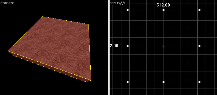 Создайте браш с размерами деформации.
 - Используйте инструмент Clip Tool в верхнем окне 2D, чтобы разрезать браш по вертикали. Это отделит левую сторону дырки:
Template:Note:ru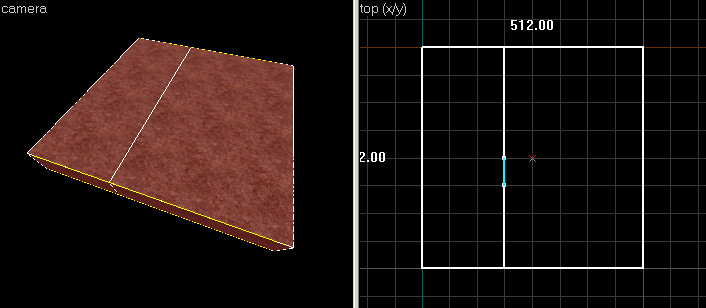 Создайте левую сторону от дырки с помощью Clip Tool.
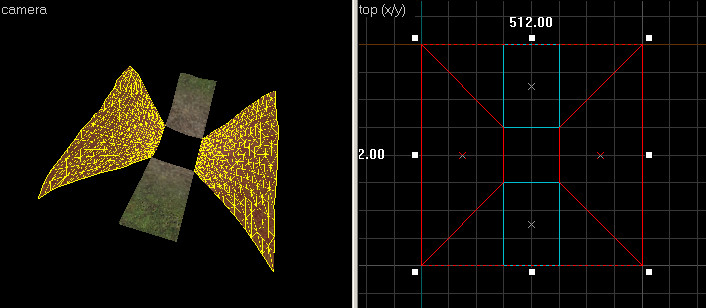
 - Используйте Clip Tool, чтобы также вырезать блок справа.
Затем выберите центральную часть инструментом Selection Tool.
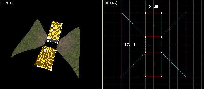
Снова вернитесь к Clip Tool и обрежьте центр браша по горизонтали два раза, чтобы создать по центру квадрат. Конечный результат должен выглядеть примерно так: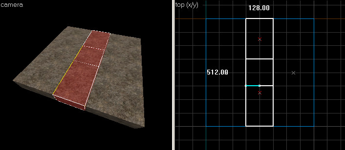 Вырежьте браш с других сторон от дырки.
 - Используя инструмент Selection Tool, выделите только что вырезанный по центру квадрат. Нажмите кнопку Delete, чтобы удалить браш, образовав дырку по центру:
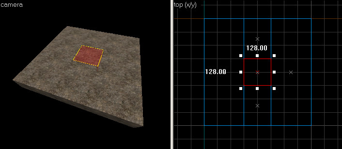 Выберите браш по центру и удалите его.
 - Инструментом Selection Tool выделите два браша по краям:
 Выберите браши.
 - Выберите Vertex Edit Tool чтобы перейти в режим редактирования вершин:
 Переключение в вертексный режим.
 - В верхнем окне 2D-вида выберите угловую точку, и перетяните ее к центру квадрата, как показано:
 Перетяните угловую точку в угол дыры.
 - Повторите эту операцию с тремя другими углами -- перетащите их к центру, как на рисунке:
 Переместите другие точки соответственно.
 - В режиме вертексного редактирования, выберите один из оставшихся двух брашей. Удерживая Ctrl также выберите другой. Выделенные части должны соответсвовать картинке:
 Выберите два браша с помощью CTRL-щелчок левой кнопкой.
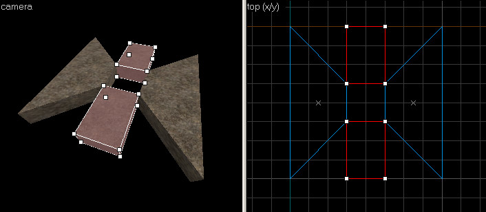
 - Перетяните внешние вершины этих брашей, чтобы они выстроились в линию с четырьмя внешними углами, как на следующем рисунке:
 Редактирование вершин брашей для соответствия с внешними краями.
 - Переключитесь на инструмент Texture Application Tool, и, зажав CTRL, в окне3D щелкайте левой кнопкой по верхней стороне всех четырех брашей. Выделите только верхнюю часть, как показано здесь:
 Выберите верхнюю грань.
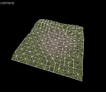
 - В диалоговом окне Face Edit переключитесь на вкладку Displacement. Нажмите кнопку Create, чтобы создать деформацию выбранных поверхностей. Теперь у вас должна быть деформация с дыркой по середине:Теперь эти деформации могут свободно рисоваться или трансформироваться. Поскольку четыре внешних края не разделены, эти деформации могут быть беспрепятственно сшиты с окружающей геометрией.
 Создайте деформации с помощью редактированных брашей.


Using clipping to add holes to existing displacements
Creating a hole where you have already have displacements is done utilizing the clip tool in combination with vertex editing. This method is not as straightforward as making a hole by creating new displacements, but it will preserve some of the shape of any existing surfaces.
Follow these steps to make a hole in the center of an existing displacement surface:
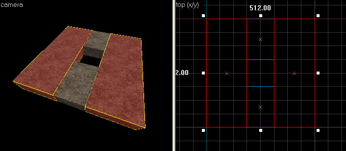
- Select the displacement you wish to create a hole in with the Selection Tool:
 The target displacement.
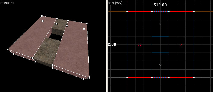
 - Use the Clip Tool to cut the displacement in the vertical direction. This split will be the left side of the hole:
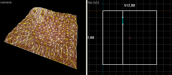 Using the Clip Tool to create the left side of the hole.
 - Use the Clip Tool to cut the brush three more times -- Cut the displacement on the right side, as well as two times horizontally, to create a square in the middle:
 Cut the brush for the other sides of the hole.
 - Using the Selection Tool, select the displacement square in the middle that was a result of the clips you made. Press the Delete key to delete the displacement, leaving a hole in the center:
 Select the center brush and delete it.
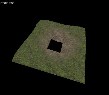 The center displacement has been deleted, leaving a hole.
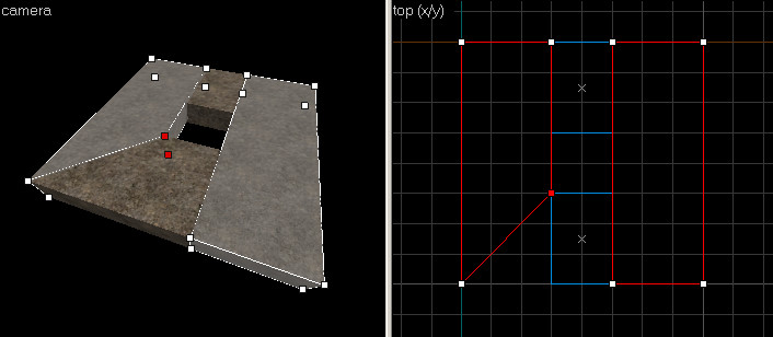
 - We're not finished yet, because the displacement still needs to be fixed up so it can Sew properly to neighboring surfaces.Switch to the Clip Tool and select the displacement on the right side. In the Top 2D View, use the Clip Tool to trim off the corner piece of the displacement.
Make sure the clip snaps to corners on the grid, or the displacement will get destroyed: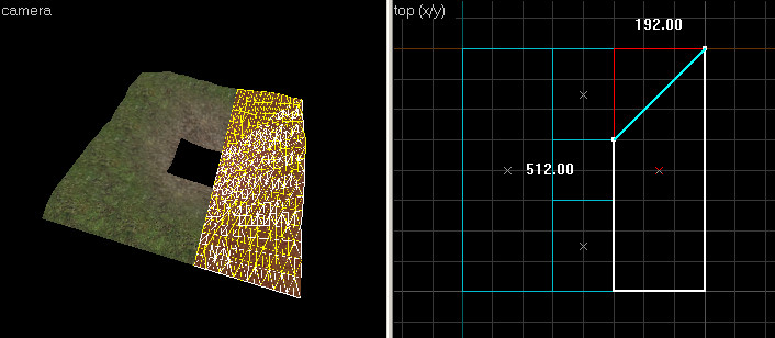 Use the Clip Tool to trim the displacement towards the hole.
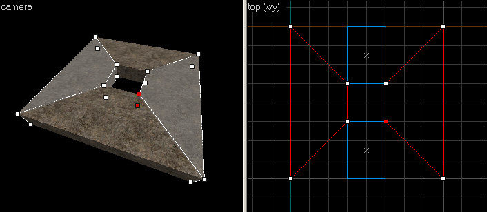
 - Repeat the same operation for the other corner of the displacement, as well as the displacement on the left side -- clip each of the corners to create the edges as shown:
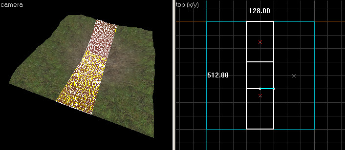
 Clip the the edges on the left and right side.
 - Switch to the Vertex Edit Tool. Select one of the remaining two top and bottom displacements. Hold down CTRL and select the other one as well. Your selection should match this image:
 Select the other two displacements using Ctrl+left click.
 - Drag the outer vertices of these two displacements to line up with the four outer corners, to match the following image:
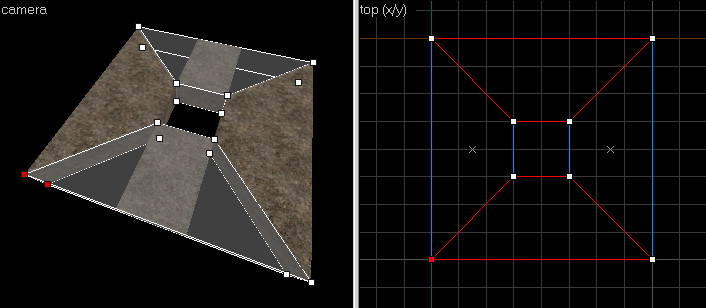
 Vertex edit the displacements to fit the outer edges.
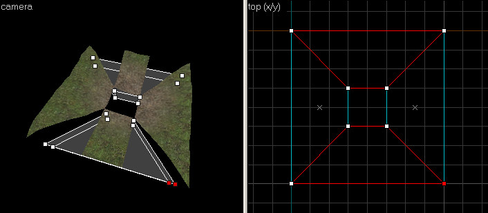
 - Switch to the Face Edit Tool, click the Displacement tab of the Face Edit dialog. Select all of the displacement surfaces by left-clicking one of them in the 3D View, then holding down CTRL and left-clicking the remaining faces. Only select the four displacements.
Notice how the displacements edges do not line up, due to the clipping that was done: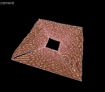 Select all the displacements in Face Edit Mode.
 - Click the Sew button. The displacements should connect to each other like this:
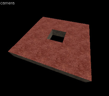
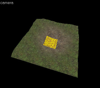
 The final displacements with a hole, after the Sew operation.


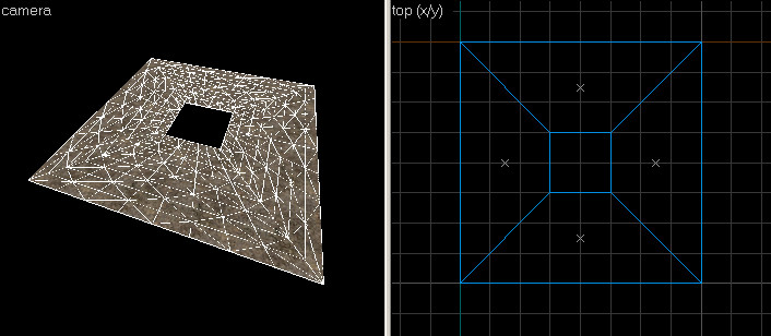
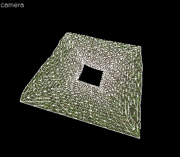
These displacements can now be freely painted or transformed. Because the four outside edges are not split, these displacements can be sewn to and surrounding geometry seamlessly.
The following images demonstrate how the displacement geometry created in the previous steps can be attached to other displacements:


See Also
| Статьи об окружающей среде | |
|---|---|
| Текстуры неба и создание неба | |
| Создание рельефа местности и деформация поверхностей | Деформированные поверхности • Создание отверстий в деформированных поверхностях • Цифровые модели местности • Создание рельефа в Worldmachine |