Texturing in XSI
The aim of this tutorial is to introduce you to the world of texturing and explain how to work your textures in ![]() Source. It's assumed that you have read the tutorial on the basics of XSI: XSI Beginner Tutorial.
Source. It's assumed that you have read the tutorial on the basics of XSI: XSI Beginner Tutorial.
Texturing Outline
In order to view your model in Source, you have to texture it with at least a plain white texture, or else it will be purple boxed or possibly not even show up at all. Here we will discuss the principles of texturing, what you should look for in good textures, and how to get those textures into Source and Hammer so you can actually use your model. It is assumed you know how to make a TGA file and also how to compile it for Source using VTEX. The proper steps to texturing your model are as follows:
- Find a texture and convert to TGA
- Import into XSI
- Map the texture onto your model
- Convert TGA to VTF
- Export model, place into Hammer, compile, view in-game!
Texturing Basics
Whether you want to or not, it is essential to understand the basics of texturing before you even attempt to texture a model.
UV or Not UV—That is The Question
The basics of texturing involve some simple math to map coordinates in a 2D plane to a 3D model. In order to do this, the 2D texture has its own coordinate system in the U and V axis. U is the horizontal axis and V is the vertical axis of your texture, and they both go from 0 to 1 (e.g., 0.5,0.5 would be the middle of the texture). An object in XSI can only be mapped with ONE texture, possibly, so when building your textures you must combine several into one 512x512 image and use that for all your objects.
Normal Mapping and Other Peculiarities
A bump map is a texture that changes the way light interacts with the applied surface, much like small bumps on an object in the real world. There are 2 types of bump maps. Grayscale (black and white) and RGB normal maps. Bump maps (Called height maps in some engines) change the depth of the rendered pixel (Since we are taking about pixel shaders here), so its job is to give the illusion of depth. Height maps are useful for rivets, screws, gashes and stuff that isn't very complex. Normal maps are RGB (Red, green, blue) images depicting where there is change in the angle of the rendered pixel. This is much more useful for intricate details like folds, wrinkles, complex surfaces like faces and bodies, unlike height maps. There are several tutorials out there on how to make and apply normal mapped textures, but that is beyond the scope of this article. It usually involves creating a low poly game mesh and a high poly detail mesh, then UV mapping the low poly and baking the high-res model's polygon normals into a texture. You should NOT apply a normal map in XSI unless you are doing it to show off how your model will look before compiling it.
Using Ultimapper in XSI for Normal Map Creation
Ultimapper is the tool used within XSI for rendering out normal maps from a high resolution mesh for mapping onto your game resolution mesh. General workflow is as follows; create a group of high resolution objects that define the detail areas of your mesh, or create a subdivided refinement of your base mesh. If you're using more than one object to make a detailed mesh, use the edit: group command from the Main Command Panel (MCP). Once defined and selected, you can render out your tangent space normals, high resolution ambient occlusion maps for texturing, and any other material information you may need (in the albedo map). One note of caution, you need to invert the up and down channel of the resulting normal map to match the rendering inside of the engine. Open the normal map in photoshop, open the channel section in the layer window, then select the green channel. Now invert this channel (Ctrl+I). Save this and re-export your VTF. (this refers to version 5 and up of XSI, previous versions use the "GPU surface FX" property, which functions in a similar manner).
Texturing in XSI
Now you can begin getting textures into XSI and pasting them onto our models! Follow closely and look at the images if you get lost.
Importing a Texture
It's a good idea to use TGA (Targa) files because they are compressionless and are the same format that will be used by VTEX to create the HL2 materials, therefore WYSIWYG. First you need to make the texture local to our cube so that it will display properly, and more importantly, export properly.
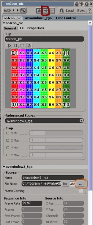
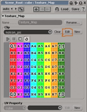
Click Render at the top of the screen, go down to Get - Texture, then press Image. Now you are ready to start texturing (see Left Image). What you see in front of you is the XSI default mapping texture, which is good to use if you are trying to see how certain sections of your model will map to a texture. Click edit next to the name of the texture (it should be nolcon_pic) at the top of the window (circled in the pic). This will bring up a new property window that you can use to change the image properties of this texture. Go to about the middle of the page using the scroll bar, and where you see "C:\somedir" click the … button on the far right (circled in pic) and find the image you want to use as a texture on your computer. Congratulations your image is now imported into XSI, click the little left arrow on the top of the current properties window to return to the Texture Map properties page.
Following the UV–Textured Road
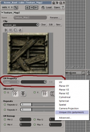
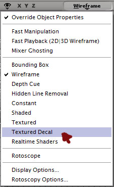
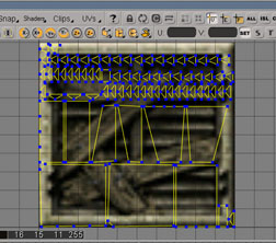
Having imported your texture into XSI (in the pic you can see it is a new image, and it should be different in yours too), we can now map it to our object. With the object you want to texture selected, press the New button in the Texture Projection box. Then go down to Unique UV's (polymesh) to create a UV mapping of our model's mesh for use with our texture. Now to view our texture on the model, do what's depicted in the image titled Getting your view setup, in the 3D view. Now press Alt+7 to open the Texture Editor Window. Your object has been broken down into its polygons and laid out naked onto our texture!
The Texture Editor
So far, you have taken the TGA texture on your computer and imported it into XSI. Then you created a UV mapping of our object. Now we have our mapped polygons laid out on our texture ready to go.
The Interface
Orange Box
In this box you have your basic select, move, and manipulate tools. The button on the far left is your select button and it will select depending on the settings you put in the upper blue box (more on that later). The next button is the move button, and will move whatever you click and drag depending on what is selected in the upper blue box. The button after that is the crop button and can be used to crop out your texture image. The last three buttons are for collapsing your selection into a single point, a horizontal line, or a vertical line respectively.
Red Box
In this box are all the buttons you need to start off wraping your model onto the texture correctly. On the left is the linear wrapping button. Think of this as if you take your texture and paste it onto whatever surface you select. The second button is for cylindrical wrapping and is like taking a soda can and cutting it down vertically one side and pulling it apart into a sheet. This is basically what you are doing to the polygons of your selection (Good for a soda can model). The third button is spherical mapping, and as its name states, is good for mapping a texture onto a sphere.
Yellow Box
There are only 2 buttons you should worry about here. The one with the circular arrows checks to see what you have selected in the 3D view and applies that selection to the texture editor, and the one with the horizontal arrows does the opposite. Very useful if you are mapping certain objects and it isn't selecting right in the texture editor.
Blue Box
In this upper blue box you designate what things you want to select or move using the tools from the orange box. This is exactly like what you have in the modeling portion of XSI only it is in the texture editor. V is for vertex, E is for Edge, and P is for polygon. The lower blue box is the same things in the modeling portion of XSI in which you can Scale, Rotate, and Translate whatever is selected. Unlike the move arrow in the orange box, when you select one of these, it applies to the entire selection.
Green Box
In the green box are your commands for showing and hiding selections, just like in Hammer. Press the S button to show only what is selected. Press the H button to show everything not selected. Press the A button to show everything.
Texturing Our Cube
Now you are going to take your texture and apply it to our cube. The cube shown in the picture has some extra details.
Back to the Texture Editor
In the 3D view with ray-cast polygon selection, select one side of your cube. Now back in the texture editor click the linear wrapping button and select Best Fit. This will instantly place all four vertices of the cube side onto the texture at (0,0);(0,1);(1,0);(1,1) and make a perfect match! Try experimenting by selecting all four sides of the cube and doing cylindrical mapping.
That about does it for mapping textures, its all about manipulating the polygons in the texture editor with the orange and blue boxed buttons in order to create the appearance you want.
Selecting Good Textures
All I can say about this is, SEARCH SEARCH SEARCH! Google image search is my friend, and it should be yours too. And there is no need for a direct shot when texturing because as we discussed before it's all about how you map it!
