Reshaping solids
Once you've created a simple, textured solid, you can use Hammer's tools for refining your work. These tools include vertex manipulation, face splitting, clip planes and carving. Each of these tools lets you customize your solids by modifying the basic shapes you started with. You will find that you can achieve the same or similar effect using different tools; some are just faster and easier than others when it comes to making the precise change you are trying to make.
Vertex Manipulation
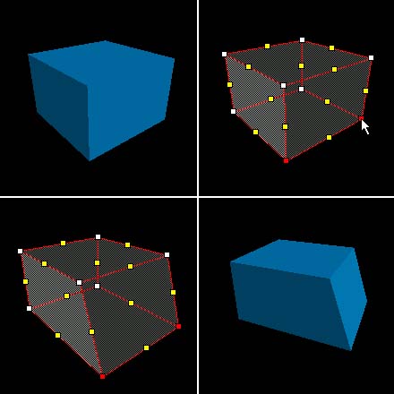
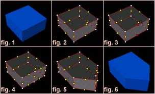
Vertex manipulation allows you to move individual vertices and edges of a solid, easily creating irregular shapes. This lets you make shapes that are impossible with plane clipping, and extremely difficult to do with carving. Vertex manipulation is also useful for modifying specific pieces of a group of objects, where resizing would interfere with other objects in the group.
Vertices and Edges
A vertex (or plural, vertices) is a corner of a solid. Moving one vertex will not affect any other vertex, but it will change the position of any edges associated with it. An edge is a point between two vertices which, when moved, will change the position of its two associated vertices, as well as their associated edges (no other vertices are effected besides the first two).
To edit the vertices of an object:
- Select the object(s) you would like to use vertex manipulation on.
- Select the Vertex Tool from the Map Tools Toolbar. The selected solid will turn into a wireframe image with partial shading. Vertices will be marked as white dots, and edges as yellow dots.
- Click on the vertices/edges you want to move. They will be highlighted in red. Note that you can move both vertices and edges.
- You can either drag the selected vertices or edges with the mouse, or move them in the selected 2D view using the arrow keys.
Face Splitting
Face splitting allows you to add additional faces to a brush. This is a useful tool when you want to add complexity to an object in your level. Simply select two opposing edges (fig. 3) (Two opposing vertices on a flat plane work as well) and press Ctrl+F. This will turn the two edges into vertices, and place a new edge between them (fig.4).
Face splitting between opposing vertices can be extremely useful for fixing previously invalid solids with non-flat faces. A quadrilateral can be split into two triangles this way, but care must be taken that the resulting brush is not concave - the two new faces must not 'dip' in the middle.
While no longer as important since Source's introduction of displacements, vertex manipulation involving a great deal of face splitting used to be a very powerful, efficient way of building realistic terrain for the original Half-Life engine.
Vertex Scaling
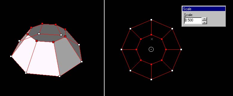
Vertex scaling allows you to select a number of vertices and change their scale in relation to each other.
To scale a set a vertices on an object:
- Select the object(s) you would like to scale vertices on.
- Select the Vertex Tool from the Map Tools Toolbar. The selected solid will turn into a wireframe image with partial shading. Vertices will be marked as white dots, and edges as yellow dots.
- Click on the vertices/edges you want to scale. They will be highlighted in red.
- Press ALT+E to enter to bring up the Scale dialog box.
- Alter the center of the scale operation by clicking and dragging the white circle in the center of the vertex selection.
- Change the Scale value to alter the selected points. You can press the up or down arrows to move in 0.1 increments, or enter a scale value directly in the text area. The scale changes will automatically be reflected on the selected object.
- Press the ↵ Enter or ESC key when you are done scaling to close the Scale dialog box.
Clip Planes
Clip planes let you make a precise cut in a solid, dividing it into two pieces. You then have the option of keeping one or both of the resulting two solids. You may find using Clip Planes quicker and more efficient than carving or vertex manipulation.
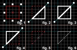
- Select the object to be clipped. (fig. 1)
- Select the Clip Plane button on the Map Tools toolbar.
 Note:You can cycle through the clip modes by clicking on the clip plane button, or by pressing ⇧ Shift+X (fig.2, 3, 4). You can move both points of the clip line by holding CTRL and dragging one point of it.
 - Drag a line across the selected object. (fig. 2) This is the clip line. The part of the object to be kept will be highlighted in thick white lines.
- When you are satisfied with the resulting object, press Enter to perform the clip. (fig. 5, 6)
Hammer has a feature to display the size of the solid area of the clipped brush. This is useful if you're trying to clip a brush to an exact size.
To toggle this on and off, have a 2D view in focus and press the "o" (lowercase) hotkey.
Carving
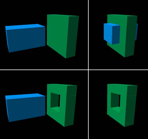
In Hammer, any solid can be used to carve a volume out of other solids. For example, you can place a solid within the room's wall and tell Hammer to subtract the solid from the wall -- effectively punching a hole right through the wall! This feature is not limited to using cubic shapes as a carving tool: any solid -- cylinders, cubes and wedges -- can be used to carve other solids.
To carve objects from surrounding solids:
- In this step, you have the object you want to carve into (in green), and the object you will be carving with (in blue). The blue object should be selected.
- Position the carving object so that it is where you want the hole to be.
- Select Carve from the Tools Menu. You can also press CTRL+⇧ Shift+C or the Carve button on the Map Operations toolbar.
- Either delete the object you used to make the carve, or use it to fill the hole. (For example, use the piece carved out of a doorway as the door.)
In the picture above, you can see that the green object is now broken into four separate objects. This is because the game engine cannot handle concave objects, and Hammer has broken it into convex pieces.
Decimal Loss after Reload
Some brushes may appear to be valid yet will change after saving and reloading the map or running the clip plane tool. The reason is because the map file describes solids as a set of planes while Hammer thinks of them as a set of vertices. A plane, by definition, is a flat surface extending to infinity in all directions. When Hammer reads the map file, it finds the places where three planes intersect and creates vertices at those locations. (This is why concave brushes are impossible.) The issue is that the numbers used to describe planes and vertices have a limited number of decimal points. Although the vertices may lie perfectly on the grid when a brush is created, the resulting planes may have many decimal places. If the decimal limit is reached, the planes will be slightly different. Shapes with such issues may develop visible seams along the edges where it is possible to see through the brush (although these may not appear in-game, see note below.)
Hammer++ similarly also fixes this issue.
