Source 2/Docs/Level Design/Basic Construction/Mesh Editing 2: Difference between revisions
KubeKing4556 (talk | contribs) m ("or are" -> "or when" grammar fix) |
m (Nesciuse moved page Source 2/Docs/Level Design/Basic Construction/Mesh Editing 2/en to Source 2/Docs/Level Design/Basic Construction/Mesh Editing 2 without leaving a redirect: Move en subpage to basepage) |
||
| (8 intermediate revisions by 5 users not shown) | |||
| Line 1: | Line 1: | ||
{{ | {{LanguageBar}} | ||
__TOC__ | |||
The previous article covered the basics of manipulating faces, edges, and vertices, which are the building blocks of any shape in Hammer. This article will cover building something structurally recognizable using some additional important tools. | |||
A simple arched bridge, while a complex set of operations in the previous iteration of Hammer, using the tools provided here it is fairly straightforward but uses a workflow that is somewhat different. | A simple arched bridge, while a complex set of operations in the previous iteration of Hammer, using the tools provided here it is fairly straightforward but uses a workflow that is somewhat different. | ||
| Line 10: | Line 10: | ||
[[File:Mesh-editing-2-2-cuboid-and-cylinder.PNG|300px|thumb|right|Create the base component meshes.]] | [[File:Mesh-editing-2-2-cuboid-and-cylinder.PNG|300px|thumb|right|Create the base component meshes.]] | ||
Start a new map. Either '''File''' -> '''New''' or {{ | Start a new map. Either '''File''' -> '''New''' or {{Key|Ctrl|N}}. | ||
Create a mesh object with the '''Block''' tool to create the top of the bridge. See the image for an example. | Create a mesh object with the '''Block''' tool to create the top of the bridge. See the image for an example. | ||
| Line 17: | Line 17: | ||
# Go into '''Meshes''' mode, then create a block the rough size of your bridge. | # Go into '''Meshes''' mode, then create a block the rough size of your bridge. | ||
# First switch the block type to a cylinder ('''Block Tool''' > '''Geometry Type: cylinder''') | # First switch the block type to a cylinder ('''Block Tool''' > '''Geometry Type: cylinder''') | ||
# Set the ''' | # Set the '''Number of sides:''' to 32. | ||
# Drag in the 3D view to create the block and press {{ | # Drag in the 3D view to create the block and press {{Key|Enter}}. | ||
{{tip|As in the past, {{ | {{tip|As in the past, {{Key|[|]}} can be used to lower and raise the size of the grid.}}{{clr}} | ||
[[File:Mesh-editing-2-3-cylinder-in-place.PNG|300px|thumb|right|Move and resize the cylinder to fit.]] | [[File:Mesh-editing-2-3-cylinder-in-place.PNG|300px|thumb|right|Move and resize the cylinder to fit.]] | ||
| Line 26: | Line 26: | ||
More than likely, rotating and resizing the cylinder will be required to match the mesh object for the top of the bridge. Set things up so the ends of the cylinder are flush with the sides of the cuboid as shown. | More than likely, rotating and resizing the cylinder will be required to match the mesh object for the top of the bridge. Set things up so the ends of the cylinder are flush with the sides of the cuboid as shown. | ||
* To easily move around the entire cylinder, make sure you are in '''Meshes''' mode, and use '''Translate''' {{ | * To easily move around the entire cylinder, make sure you are in '''Meshes''' mode, and use '''Translate''' {{Key|T}} and '''Rotate ''' {{Key|R}} on the mesh. Use '''Scale''' {{Key|E}} to match the faces of the two meshes. | ||
* You can also use '''Translate''' while in ''' | * You can also use '''Translate''' while in '''Faces''' mode to align the faces precisely with the two mesh objects. | ||
Hammer does not have a boolean operator so instead of carving the cylinder from the cuboid the task can be accomplished by flipping some of the faces and sewing the remaining arch into the bridge mesh. | Hammer does not have a boolean operator so instead of carving the cylinder from the cuboid the task can be accomplished by flipping some of the faces and sewing the remaining arch into the bridge mesh. | ||
| Line 38: | Line 38: | ||
Switch to '''Faces''' mode, then select then delete the three faces on the cuboid which are intersected by the cylinder: The front, the back, and the bottom faces. While we could potentially slice them up to match the cylinder (covered later), it is easier to delete them and use the remaining three faces as a scaffold for creating new ones.{{clr}} | Switch to '''Faces''' mode, then select then delete the three faces on the cuboid which are intersected by the cylinder: The front, the back, and the bottom faces. While we could potentially slice them up to match the cylinder (covered later), it is easier to delete them and use the remaining three faces as a scaffold for creating new ones.{{clr}} | ||
[[File:Mesh-editing-2-5-face-selection.PNG|300px|thumb|right|Using {{ | [[File:Mesh-editing-2-5-face-selection.PNG|300px|thumb|right|Using {{Key|Shift}}-double-click to select a set of connected faces.]] | ||
Some useful additions in Hammer are the many ways of selecting multiple faces. Double-clicking on a mesh in ''Faces'' mode selects all faces, for example. Try that on the cylinder object to see how it works. | Some useful additions in Hammer are the many ways of selecting multiple faces. Double-clicking on a mesh in ''Faces'' mode selects all faces, for example. Try that on the cylinder object to see how it works. | ||
* Double click to select all faces on a mesh. | * Double click to select all faces on a mesh. | ||
* {{ | * {{Key|Alt}}+Double click selects all faces on a similar plane | ||
* Selecting one face then {{ | * Selecting one face then {{Key|Shift}}+Double click on another face further down will select the last face in addition to the faces in between. | ||
For example, selecting one face then {{ | For example, selecting one face then {{Key|Shift}}+Double clicking on another face will select that last face and all faces in-between: | ||
# Select the first face on the cylinder that's "inside" the bridge volume. | # Select the first face on the cylinder that's "inside" the bridge volume. | ||
# Hold down {{ | # Hold down {{Key|Shift}} and double-click the last face inside the arch (as in the screen shot). | ||
# Use '''Invert selection''' {{ | # Use '''Invert selection''' {{Key|Ctrl|I}} to invert the selection faces. | ||
# Press {{ | # Press {{Key|Delete}} to get rid of the non-arch faces (''not'' {{Key|Backspace}}).{{clr}} | ||
[[File:Mesh-editing-2-5-flip-faces.png|300px|thumb|right|Using {{ | [[File:Mesh-editing-2-5-flip-faces.png|300px|thumb|right|Using {{Key|F}} to flip face normals.]] | ||
The arch is setup but the faces look incorrect, the faces are inverse of what they should be. | The arch is setup but the faces look incorrect, the faces are inverse of what they should be. | ||
| Line 61: | Line 61: | ||
To flip the faces so that the normal is facing down, thusly completing the arch, the following is required: | To flip the faces so that the normal is facing down, thusly completing the arch, the following is required: | ||
# In '''Faces''' mode, double-click on the curved faces to select them all. | # In '''Faces''' mode, double-click on the curved faces to select them all. | ||
# Use '''Flip normals''' {{ | # Use '''Flip normals''' {{Key|F}}. This will invert the normal and should look like the image. | ||
{{note|Hammer's mesh editing makes it difficult to create particularly unpleasant solids. It'll generally flip ''all'' faces in a mesh, rather than create something horrible. It can be a challenge to create broken meshes but if you need to flip things back, pressing {{ | {{note|Hammer's mesh editing makes it difficult to create particularly unpleasant solids. It'll generally flip ''all'' faces in a mesh, rather than create something horrible. It can be a challenge to create broken meshes but if you need to flip things back, pressing {{Key|F}} again will simply invert the faces again.}}{{clr}} | ||
[[File:Mesh-editing-2-6-about-to-bridge.PNG|300px|thumb|right|Selecting edges to connect.]] | [[File:Mesh-editing-2-6-about-to-bridge.PNG|300px|thumb|right|Selecting edges to connect.]] | ||
To sew the arch mesh into the upper bridge mesh click on '''Edges''' mode (or {{ | To sew the arch mesh into the upper bridge mesh click on '''Edges''' mode (or {{Key|2}}), then select one of the edges on the bottom of the cuboid, then one at the end of the arch as in the provided image. | ||
{{tip|Notice the selected edges are drawn with ragged-looking edges. This is to indicate a discontinuity in the mesh; an "open" edge.}} | {{tip|Notice the selected edges are drawn with ragged-looking edges. This is to indicate a discontinuity in the mesh; an "open" edge.}} | ||
Using the '''Bridge''' tool will bridge the gap between two unconnected edges with a new face. Press {{ | Using the '''Bridge''' tool will bridge the gap between two unconnected edges with a new face. Press {{Key|B}} to bridge the two edges that were selected. | ||
With the face created, stay in '''Edges''' mode and select the opposite two edges and press {{ | With the face created, stay in '''Edges''' mode and select the opposite two edges and press {{Key|B}} again to create a second face. The result should be a continuous loop of faces going around the top, end, underside and other end of the bridge, with two big "n"-shaped gaps either side.{{clr}} | ||
[[File:Mesh-editing-2-7-about-to-create-face.PNG|300px|thumb|right|Double-click to select the open edge loop.]] | [[File:Mesh-editing-2-7-about-to-create-face.PNG|300px|thumb|right|Double-click to select the open edge loop.]] | ||
While still in '''Edges''' mode, double-click on one of the edges leading around one of the gaps to select the entire loop as shown. To create a new face, use '''Polygon''' {{ | While still in '''Edges''' mode, double-click on one of the edges leading around one of the gaps to select the entire loop as shown. To create a new face, use '''Polygon''' {{Key|P}}. This will fill in the gap. Do the same on the other side and the end result is a simple bridge shaped arched solid.{{clr}} | ||
== Adding Detail == | == Adding Detail == | ||
| Line 89: | Line 89: | ||
# In '''Faces''' mode, angle the view so you can see the top and one end of the bridge. | # In '''Faces''' mode, angle the view so you can see the top and one end of the bridge. | ||
# Enable the '''Cut tool''' {{ | # Enable the '''Cut tool''' {{Key|C}} mode. | ||
# Move the mouse over the edge connecting the top and end of the bridge. This shows where it will add a new vertex. | # Move the mouse over the edge connecting the top and end of the bridge. This shows where it will add a new vertex. | ||
# Click with {{ | # Click with {{Key|LMB}} around 8 units from the side of the bridge, then 8 units down on the back of the face. | ||
# Continue across to near the other side of the bridge. The aim here is to create a shallow "U" shape, with the walls of the bridge and the new road surface (see screenshot). | # Continue across to near the other side of the bridge. The aim here is to create a shallow "U" shape, with the walls of the bridge and the new road surface (see screenshot). | ||
#: {{tip|The edge being added turns orange when it's aligned with the grid. This is useful when working on irregularly-shaped objects or when fighting against perspective.}} | #: {{tip|The edge being added turns orange when it's aligned with the grid. This is useful when working on irregularly-shaped objects or when fighting against perspective.}} | ||
# Once you're back at the main edge, rotate the view to the other end of the bridge. Create the same cuts on that side. | # Once you're back at the main edge, rotate the view to the other end of the bridge. Create the same cuts on that side. | ||
# After making the second "U" shape, connect it back to the first end of the bridge again, making a complete connection. After making the final point, press {{ | # After making the second "U" shape, connect it back to the first end of the bridge again, making a complete connection. After making the final point, press {{Key|Enter}}. This should cut the top face into three faces: two narrow at the sides for the tops of the walls, and one wide for the road surface. See the second screenshot for a visual description. | ||
#:{{note|You can use {{ | #:{{note|You can use {{Key|RMB}} and other navigation shortcuts such as "WASD" to move the camera without stopping the cutting operation.}} | ||
{{clr}} | {{clr}} | ||
| Line 105: | Line 105: | ||
# In '''Faces''' mode, select and delete the large top face and the two small ones at either end. | # In '''Faces''' mode, select and delete the large top face and the two small ones at either end. | ||
# Then in '''Edges''' mode, select the three edges at either end. See the screenshot for details. | # Then in '''Edges''' mode, select the three edges at either end. See the screenshot for details. | ||
# Now use '''Bridge''' {{ | # Now use '''Bridge''' {{Key|B}}. The Bridge tool will work between multiple groups of edges, so long as there's the same number on each side of the gap. You should now have walls and a flat road surface.{{clr}} | ||
== Further Exploration == | == Further Exploration == | ||
| Line 112: | Line 112: | ||
For practice, try refining the model further using the tools taught so far. | For practice, try refining the model further using the tools taught so far. | ||
* Go to '''Faces''' mode, select the road surfaces and adjust the height with '''Translate''' {{ | * Go to '''Faces''' mode, select the road surfaces and adjust the height with '''Translate''' {{Key|T}}. | ||
* Try using the '''Cut''' {{ | * Try using the '''Cut''' {{Key|C}} tool to add additional details. Cut faces into smaller ones, either adding new vertices on faces or edges, or by connecting vertices together with new edges. | ||
* To remove an edge and merge any connected faces, select the edge and press {{ | * To remove an edge and merge any connected faces, select the edge and press {{Key|Backspace}}. This keeps will keep a face intact. | ||
* After adding a few extra edges through cutting and then extruding the faces (with {{ | * After adding a few extra edges through cutting and then extruding the faces (with {{Key|Shift}}), the edges and faces can be moved around with '''Translate''' to rapidly add realistic details to the mesh. | ||
{{clr}} | {{clr}} | ||
| Line 121: | Line 121: | ||
[[File:Mesh-editing-2-11-extra-credit.PNG|600px|thumb|center|The bridge mesh with some additional edges inserted.]] | [[File:Mesh-editing-2-11-extra-credit.PNG|600px|thumb|center|The bridge mesh with some additional edges inserted.]] | ||
'''Next''': [[ | '''Next''': [[Source 2/Docs/Level Design/Basic Construction/Mesh Editing 3|Mesh Editing 3]]{{Hla tools topicons}} | ||
{{Cs2 tools topicons}} | |||
{{ | {{Dota 2Tools topicons}} | ||
Latest revision as of 09:57, 12 July 2024
The previous article covered the basics of manipulating faces, edges, and vertices, which are the building blocks of any shape in Hammer. This article will cover building something structurally recognizable using some additional important tools.
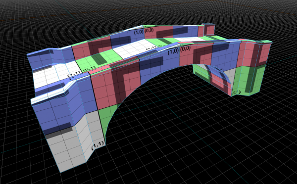
A simple arched bridge, while a complex set of operations in the previous iteration of Hammer, using the tools provided here it is fairly straightforward but uses a workflow that is somewhat different.
Blocking Out the Shape
Start a new map. Either File -> New or Ctrl+N.
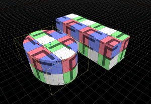
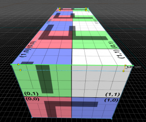
Create a mesh object with the Block tool to create the top of the bridge. See the image for an example.
Next create the cylinder block to act as the curve of the arch:
- Go into Meshes mode, then create a block the rough size of your bridge.
- First switch the block type to a cylinder (Block Tool > Geometry Type: cylinder)
- Set the Number of sides: to 32.
- Drag in the 3D view to create the block and press ↵ Enter.
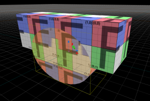
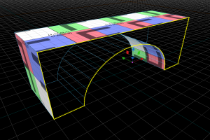
More than likely, rotating and resizing the cylinder will be required to match the mesh object for the top of the bridge. Set things up so the ends of the cylinder are flush with the sides of the cuboid as shown.
- To easily move around the entire cylinder, make sure you are in Meshes mode, and use Translate T and Rotate R on the mesh. Use Scale E to match the faces of the two meshes.
- You can also use Translate while in Faces mode to align the faces precisely with the two mesh objects.
Hammer does not have a boolean operator so instead of carving the cylinder from the cuboid the task can be accomplished by flipping some of the faces and sewing the remaining arch into the bridge mesh.
When it's lined up, it's now ready for the next step.
Sewing the Arch
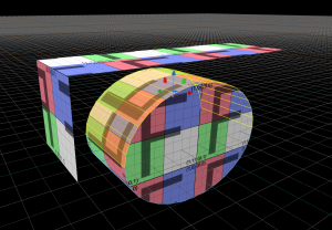
Switch to Faces mode, then select then delete the three faces on the cuboid which are intersected by the cylinder: The front, the back, and the bottom faces. While we could potentially slice them up to match the cylinder (covered later), it is easier to delete them and use the remaining three faces as a scaffold for creating new ones.
Some useful additions in Hammer are the many ways of selecting multiple faces. Double-clicking on a mesh in Faces mode selects all faces, for example. Try that on the cylinder object to see how it works.
- Double click to select all faces on a mesh.
- Alt+Double click selects all faces on a similar plane
- Selecting one face then ⇧ Shift+Double click on another face further down will select the last face in addition to the faces in between.
For example, selecting one face then ⇧ Shift+Double clicking on another face will select that last face and all faces in-between:
- Select the first face on the cylinder that's "inside" the bridge volume.
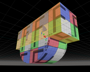
- Hold down ⇧ Shift and double-click the last face inside the arch (as in the screen shot).
- Use Invert selection Ctrl+I to invert the selection faces.
- Press Delete to get rid of the non-arch faces (not ← Backspace).
The arch is setup but the faces look incorrect, the faces are inverse of what they should be.
An important concept in 3D editing software is the face normal. The faces are generally one-sided polygons - the normal indicates the side on which the polygon has solidity. So flipping a face's normal has the effect of turning it inside-out - flipping the normals on a cube, for example, would turn it into a hollow box which you can see into from the outside. While not something that would exist in reality, it can be paired with an un-flipped, slightly larger cube to give a conventionally hollow cube.
To flip the faces so that the normal is facing down, thusly completing the arch, the following is required:
- In Faces mode, double-click on the curved faces to select them all.
- Use Flip normals F. This will invert the normal and should look like the image.
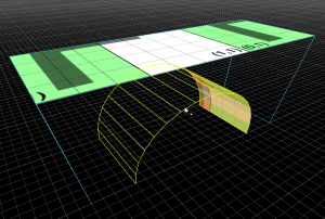
To sew the arch mesh into the upper bridge mesh click on Edges mode (or 2), then select one of the edges on the bottom of the cuboid, then one at the end of the arch as in the provided image.
Using the Bridge tool will bridge the gap between two unconnected edges with a new face. Press B to bridge the two edges that were selected.
With the face created, stay in Edges mode and select the opposite two edges and press B again to create a second face. The result should be a continuous loop of faces going around the top, end, underside and other end of the bridge, with two big "n"-shaped gaps either side.
While still in Edges mode, double-click on one of the edges leading around one of the gaps to select the entire loop as shown. To create a new face, use Polygon P. This will fill in the gap. Do the same on the other side and the end result is a simple bridge shaped arched solid.
Adding Detail
One way to add some detail to this bridge is to create walls along side the road surface at the top. One method would be to create some new meshes and either place them on top, similar to previous methods of construction, or sew them in. Instead of either of those, it is quick to simply add some edges to the existing face and then work from those.
It's worth noting that there are multiple ways to accomplish this action, this method exercises the Cut tool specifically.
- In Faces mode, angle the view so you can see the top and one end of the bridge.
- Enable the Cut tool C mode.
- Move the mouse over the edge connecting the top and end of the bridge. This shows where it will add a new vertex.
- Click with
 around 8 units from the side of the bridge, then 8 units down on the back of the face.
 - Continue across to near the other side of the bridge. The aim here is to create a shallow "U" shape, with the walls of the bridge and the new road surface (see screenshot).
 Tip:The edge being added turns orange when it's aligned with the grid. This is useful when working on irregularly-shaped objects or when fighting against perspective.
- Once you're back at the main edge, rotate the view to the other end of the bridge. Create the same cuts on that side.
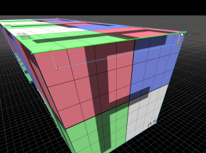
- After making the second "U" shape, connect it back to the first end of the bridge again, making a complete connection. After making the final point, press ↵ Enter. This should cut the top face into three faces: two narrow at the sides for the tops of the walls, and one wide for the road surface. See the second screenshot for a visual description.
 Note:You can use
  and other navigation shortcuts such as "WASD" to move the camera without stopping the cutting operation.
The Bridge tool will complete the new detailed bridge.
- In Faces mode, select and delete the large top face and the two small ones at either end.
- Then in Edges mode, select the three edges at either end. See the screenshot for details.
- Now use Bridge B. The Bridge tool will work between multiple groups of edges, so long as there's the same number on each side of the gap. You should now have walls and a flat road surface.
Further Exploration
For practice, try refining the model further using the tools taught so far.
- Go to Faces mode, select the road surfaces and adjust the height with Translate T.
- Try using the Cut C tool to add additional details. Cut faces into smaller ones, either adding new vertices on faces or edges, or by connecting vertices together with new edges.
- To remove an edge and merge any connected faces, select the edge and press ← Backspace. This keeps will keep a face intact.
- After adding a few extra edges through cutting and then extruding the faces (with ⇧ Shift), the edges and faces can be moved around with Translate to rapidly add realistic details to the mesh.
Next: Mesh Editing 3
