Blender Modelling Walkthrough
The following tutorial will cover the basics of creating a model in Blender for use in the Source Engine. The model being made is a soda can, to make it we will be using Blender's mesh editing and texture mapping tools.
Installation
If you haven't already done so, please go through the tutorial Installing Blender to make sure you have everything you need to go through this tutorial.
Reference
| Key | |
|---|---|
| Left Mouse Button | |
| Middle Mouse Button | |
| Right Mouse Button | |
| MW | Mouse Wheel |
| MWUp | Mouse Wheel Up |
| MWDown | Mouse Wheel Down |
| 9 | 9 on the main keyboard |
| Num9 | 9 on the Number Pad |
In this tutorial mouse and keyboard actions have been denoted with a special marking and are abbreviated. For reference, these abbreviations and denotations are listed in the table on the right.
Values that you will need to change to match those on your computer are listed in GREEN.
Getting Started

Now, if you haven't already, load Blender. Here we have are default screen on the left.
For a brief over view, Blender's workspace is divided into different areas called viewports. Each viewport area contains a different "Window Type" that can be changed by clicking on the Window Type icon. Also, every "Window Type" has a header that can be relocated to the top or bottom of the window, or be removed entirely by clicking on it with the ![]() . Blender starts with three viewports open by default:
. Blender starts with three viewports open by default:
- 1. The User Preferences Window
- 2. The 3D View Window
- 3. The Buttons Window
Will be going over these more later, but that's it for now.
Adjusting the preferences
The User Preferences Window is hidden by default with only the header visible. To make things easier to keep track of, lets turn on the view name option inside the preferences window. Position the cursor just under the "File Add Timeline... " header, it should change from a pointer to an up/down arrow. With the cursor as an up/down arrow, press the ![]() and drag the cursor towards down to about the middle of the 3D view and release it. If the "View and Controls" tab is not active, click on it, then click on the "View Name" button (to the left of the viewport) with the
and drag the cursor towards down to about the middle of the 3D view and release it. If the "View and Controls" tab is not active, click on it, then click on the "View Name" button (to the left of the viewport) with the ![]() . The position name should now be visible in the top left portion of the 3D View. When you're finished setting the options, again position the cursor under the "File Add Timeline... " header, then drag it back up to the top of the screen with the
. The position name should now be visible in the top left portion of the 3D View. When you're finished setting the options, again position the cursor under the "File Add Timeline... " header, then drag it back up to the top of the screen with the ![]() .
.

Creating the model
To start off with, save the image file below somewhere on you computer, and take note of the location. We will be using it later on in this tutorial to skin the model. For this tutorial, I've saved the image to "c:\Modeling\Blender\SourceSDK\Guide\".

Next, lets get rid of the light and camera. To select them both, first select one of them with the ![]() , select the other by holding ⇧ Shift and clicking on it with the
, select the other by holding ⇧ Shift and clicking on it with the ![]() . Now press H to hide them both from view, you can unhide them later by pressing ALT H.
. Now press H to hide them both from view, you can unhide them later by pressing ALT H.

Select the cube with the ![]() and delete it by pressing X and confirming the delete by clicking "Erase Selected" with the
and delete it by pressing X and confirming the delete by clicking "Erase Selected" with the ![]() . Add a cylinder by pressing SPACEBAR, then choosing Add > Mesh > Cylinder (if you select the wrong item, just press ESC to cancel the operation). When the "Add Cylinder" confirm window pops up, change the number of vertices to 12, then click "OK" to create it.
. Add a cylinder by pressing SPACEBAR, then choosing Add > Mesh > Cylinder (if you select the wrong item, just press ESC to cancel the operation). When the "Add Cylinder" confirm window pops up, change the number of vertices to 12, then click "OK" to create it.

Now to rename the cylinder. With the cylinder selected, switch to the edit buttons panel by pressing F9 (or by clicking on the 4 dotted square), and then replace "Cylinder" with "BlenderSoda" in the ME: and OB: boxes.

Repositioning the object and "origin" (object center)
While the "center" of the cylinder should already be at the coordinates "0 0 0", it's also in the center of the geometry itself which we don't want. Instead we need to have it at the bottom of the object, so will need to reposition it. Change to the "front" view by pressing Num1 (or clicking "View" and choosing "Front") and if the cylinder isn't already selected, do so by clicking on it with the ![]() . To move the geometry and leave the center in place, go into edit mode by pressing Tab ⇆. Make sure the entire cylinder is selected by pressing A (unselct all/select all) until everything is highlighted, then press G to go into grab mode, Z to limit movement to the Z axis, and 1 to move the geometry up 1 unit.
. To move the geometry and leave the center in place, go into edit mode by pressing Tab ⇆. Make sure the entire cylinder is selected by pressing A (unselct all/select all) until everything is highlighted, then press G to go into grab mode, Z to limit movement to the Z axis, and 1 to move the geometry up 1 unit.

Editing the mesh
Now while still in mesh edit mode, go down to the 3D Views toolbar and turn on occlusion by clicking the "Occlude Background Geometry" button (the cube icon), then change to "Face Edit Mode" by clicking on the "Face" button (the triangle next to the cube icon).

Rotate the 3D View so you can see the top of the cylinder by pressing ⇧ Shift and dragging down with the ![]() , you can also rotate the view by Num8. Next, activate brush select by pressing B twice, and then highlight the top faces by clicking them with the
, you can also rotate the view by Num8. Next, activate brush select by pressing B twice, and then highlight the top faces by clicking them with the ![]() (in brush select mode
(in brush select mode ![]() selects,
selects, ![]() deselects). If the paint brush is to big, you can reduce it's size by rolling the MWDown. Now exit brush select mode by clicking the
deselects). If the paint brush is to big, you can reduce it's size by rolling the MWDown. Now exit brush select mode by clicking the ![]() or by pressing Esc. Move the selected faces up by pressing G to grab, then press Z then 1 to bring the selected faces up 1 unit along the Z-axis and then
or by pressing Esc. Move the selected faces up by pressing G to grab, then press Z then 1 to bring the selected faces up 1 unit along the Z-axis and then ![]() to confirm.
to confirm.

Opening the UV/Image Editor
Now we need to unwrap the model, to do this we need to first open the "UV/Image Editor" in a new viewport. To do this we have to "split" the 3D view in half; move the cursor down so its at the bottom of the 3D Views toolbar and it should change into "Up/Down" arrows, when it does press the ![]() and select "Split Area" with the
and select "Split Area" with the ![]() . As you move the cursor around a vertical bar should now be following it, position the vertical bar in the center of the 3D view with the cursor and confirm the split position by clicking the
. As you move the cursor around a vertical bar should now be following it, position the vertical bar in the center of the 3D view with the cursor and confirm the split position by clicking the ![]() . The 3D viewport should now have been split in two.
. The 3D viewport should now have been split in two.

Open the UV/Image Editor in the right viewport by click on the "Window Type" icon with the ![]() , then use the
, then use the ![]() again to select "UV/Image Editor".
again to select "UV/Image Editor".

Marking the Seams

Now we could select all the cylinder's faces and pressing U to unwrap the model right now, but if we do we might get odd looking UVs. This is because Blender doesn't know where to separate the texture. To fix this we need to "mark seems" on the model. Move the cursor back into the 3D view and if you're not still in mesh edit mode for the cylinder, reactivate it by select the cylinder and pressing Tab ⇆. Change to "Edge Select Mode" by holding Ctrl and pressing Tab ⇆, when the "Select Mode" menu pops up, release Ctrl and Tab ⇆, then click on "Edges" with the ![]() .
.
To select the first seem we will be using what is know as "Edge Loop Section". Make sure nothing is already selected by again pressing A, then position the cursor so it lies near the center of one of the edges going around the top of the model. Now, while holding Alt, press the ![]() to select a "ring" of edges going around the top of the model. After selecting the edges, hold Ctrl and press E to bring up the "Edge Specials" menu and click "Mark Seem" with the
to select a "ring" of edges going around the top of the model. After selecting the edges, hold Ctrl and press E to bring up the "Edge Specials" menu and click "Mark Seem" with the ![]() . The top ring of edges should now have an orange color to them indicating a seem. Now select just one of the edges going down the side of the cylinder and again use the "Edge Specials" menu to mark another seem. Rotate the view by holding Ctrl and
. The top ring of edges should now have an orange color to them indicating a seem. Now select just one of the edges going down the side of the cylinder and again use the "Edge Specials" menu to mark another seem. Rotate the view by holding Ctrl and ![]() while the cursor is in the 3d View and dragging the cursor up until you can see the bottom of the cylinder. Now repeat the process you used to select and mark the first seem at the top of the cylinder.
while the cursor is in the 3d View and dragging the cursor up until you can see the bottom of the cylinder. Now repeat the process you used to select and mark the first seem at the top of the cylinder.

Unwrapping the model
We should be able to now unwrap the cylinder. Switch back to "Face Select Mode" (Ctrl Tab ⇆) and press A until all the cylinder's faces are selected. Next, press U to bring up the "UV Calculation" menu and select "Unwrap" with the ![]() . The model's UVs should now show up in the UV/Image Editor viewport.
. The model's UVs should now show up in the UV/Image Editor viewport.

Now let's open the texture to map the UVs onto. In the "UV/Image Editor" viewport, goto the "Image" menu and hold down Ctrl while clicking "Open" with the ![]() , doing this will open the file browser in "preview mode", allowing you to see thumbnails of images before opening them. Goto the location you saved the "RedSoda.png"
file to and use the
, doing this will open the file browser in "preview mode", allowing you to see thumbnails of images before opening them. Goto the location you saved the "RedSoda.png"
file to and use the ![]() to select it. The file name should now appear just under the directory location at the top of the file browser, click on "Open Image" to load the image into the "UV/Image Editor" viewport.
to select it. The file name should now appear just under the directory location at the top of the file browser, click on "Open Image" to load the image into the "UV/Image Editor" viewport.

Mapping the UVs
Now it's time to map the cylinder's UVs onto the image. Select the right circular face by moving the cursor over part of its' geometry and press L to select "linked geometry". The whole circular texture should now be highlighted, activate grab mode by pressing G, and drag the object over the right circle on the image. Repeat this process for the left circular texture dragging it over the left circular image. Try and position the circular textures in the center of the image they're below, then scale them up until they mostly cover the circular parts of the image below them without going outside of the circle parts. Scale them by first selecting the coordinates with L, then press S to enter "Scale Mode". By dragging the cursor away from the object the size should increase, by dragging the cursor towards the object the size should decrease, hold ⇧ Shift to lower the change on scale when moving the cursor. (note: tip, the closer the cursor is to an objects center when activating a transformation, such as Scale or Grab, the greater the influence moving the cursor will have on the transformation).

Once you finish with moving the two circular UV maps into place, press A until nothing is selected, then press B once to enter "Box Select Mode". Drag a selection box over just the top set of coordinates in the box shaped UV with the ![]() to select them. Then press G and Y to limit their movement to the Y axis. Just as you did with the circular cooridinates, try to get this top row of coordinates as close to the top of the red box shape on the image without going off of it.
to select them. Then press G and Y to limit their movement to the Y axis. Just as you did with the circular cooridinates, try to get this top row of coordinates as close to the top of the red box shape on the image without going off of it.

Once you're happy with how the coordinates are situated, choose "Images" then "Save As" from the UV/Image Editor's toolbar. Change the file name to "BlenderSoda.png" (the same name we're using for the model), press ↵ Enter to confirm, and click "Save Image" with the ![]() .
.

You can now see a preview of how the image is being mapped onto your model in the 3D view by clicking the "Draw Type" icon in the header and selecting "Textured".

Adding a material
Change to the "Shading" menu in the buttons window and click the "Materials" icon. Use ![]() to click the up/down arrows icon next to "Add New" and choose "0 Material" (if there's no "0 Material", just click add new). Change the name from "Material" to "BlenderSoda".
to click the up/down arrows icon next to "Add New" and choose "0 Material" (if there's no "0 Material", just click add new). Change the name from "Material" to "BlenderSoda".

To the far right of the panel should be a tab labeled "Texture", click on the tab next to it labeled "Map Input" and click on the UV button. This will tell Blender to use the models UV coordinates to align the material rather then the material settings.

Adding a texture
Now click on the "Texture Buttons" icon with the ![]() to bring up the texture buttons panel. As you did with the material, change the "TE:" name from "Tex" to "BlenderSoda". Click the bar under "Texture Type" and select "Image", two new button panels should show up.
to bring up the texture buttons panel. As you did with the material, change the "TE:" name from "Tex" to "BlenderSoda". Click the bar under "Texture Type" and select "Image", two new button panels should show up.

Under the panel to the far right labeled "Image", click on the up/down icon next to "Load" and choose the image we saved from the UV/Image Editor earlier, "BlenderSoda.png". Take note of where the texture is being loaded from (you can see the location by clicking the folder icon), we will need to go here later. If all has gone well, we should be ready to export the model.

Exporting the model
For the model to work inside the Source Engine, we have to convert it and the texture it uses into the formats the Source engine uses. Move the cursor back into the 3D viewport and change to object mode by pressing Tab ⇆. Make sure only the cylinder is selected, then goto file, select "Export", then choose Half-Life 2 (.smd).

An export window should pop up, select "Static Mesh", and change the export file name to "BlenderSoda.smd". Before clicking "Export", take note of where Blender is outputting the file to (in this example the folder is "c:\Modeling\Blender\SourceSDK\Guide\").

After exporting the file, goto the directory Blender used for exporting and copy the "BlenderSoda.smd" file into the games "modelsrc" directory. For this example, I'm copying to the Half-Life 2 Death Match SDK folder:
- C:\Program Files\Steam\steamapps\USERNAME\sourcesdk_content\hl2mp\modelsrc
Compiling the QC file
In the same folder above were the SMD file ("BlenderSoda.smd") was copied, create a new text document, and open it with notepad. Copy and paste the following inside:
$modelname BlenderSoda.mdl
$cdmaterials "models"
$scale 4
$surfaceprop metal
$staticprop
$body mybody "BlenderSoda.smd"
$sequence idle "BlenderSoda" fps 1
Note:
- the $scale x" value is the rate of conversion for Blender units to Hammer units. For example, if your model was 4 Blender units tall, a scale of 4 would result in a model that was 16 Hammer Units tall.}}
- the "$surfaceprop metal"
After checking over the values used in the QC file, save it into the same folder the SMD is in as "BlenderSoda.qc".
To compile the model, open the command prompt (on Windows XP, "Start > Run... > cmd")
Copy and paste the commands below into the prompt, be sure to replace USERNAME with your actual Steam login name before running the command:
"C:\Program Files\Steam\steamapps\USERNAME\sourcesdk\bin\ep1\bin\studiomdl.exe" -game "c:\program files\steam\steamapps\USERNAME\half-life 2 deathmatch\hl2mp" -notxbox "C:\Program Files\Steam\steamapps\USERNAME\sourcesdk_content\hl2mp\modelsrc\BlenderSoda.qc
The compiled QC files outputs should have been sent to the folder:
- "C:\Program Files\Steam\steamapps\USERNAME\half-life 2 deathmatch\hl2mp\models"
Converting the UV/Image to a VTF
Now we need to convert the "BlenderSoda.png" file we used to texture our model with into Valve's Texture Format. To do so, refer to the tutorial Creating a Material.
The four important thing to note here are:
- 1. the texture file has the same name as the model
- 2. the converted texture file is located in the proper folder:
- "C:\Program Files\Steam\steamapps\USERNAME\half-life 2 deathmatch\hl2mp\materials\models"
- 3. the texture file has a VMT file ("texturename.vmt") with the same name ("BlenderSoda.vmt") and folder location ("hl2mp\materials\models") as the texture file
- 4. the VMT file has the proper values assigned to it:
"VertexLitGeneric"
{
	"$basetexture" "models/BlenderSoda"
	"$model" 1
}
Testing the model compile
Lastly, after you have converted the model and texture into the proper format, it's time to check and see if everything went according to plan.
- Bring up Steam, goto the tools tab, and open the Source SDK
- Make sure you have the right game engine and game selected,
- open the Model Viewer, and with the
 , click on "File" then "Load Model".
 - Using the model browser, locate the file "BlenderSoda", and open it.

Hopefully now you'll be looking at your fully compiled and textured model.
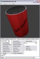
prop in the Model Viewer
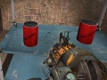
prop in-game

