User talk:Tehrasha

From Valve Developer Community
Jump to navigation Jump to search

Blender :: Animated Modelling for Source A Quick-n-Dirty Tutorial

Examples given in this tutorial were performed with Blender 2.57, and the Blender SMD Tools add-on written by Tom Edwards and should be applicable to future releases of the Blender 2.5x series. Much of the basic modelling instruction also applies to older versions of Blender, but many of the menus and keyboard shortcuts have changed.

Examples of model exporting and compiling in this tutorial use Team Fortress 2 as the platform, however, it should work with any Source based game. (CS:S, GMod, DoD, HL2, L4D, etc..)

This tutorial will not include detailed instruction on basic modelling and assumes that the user has at least a very basic knowledge of Blender and 3D modelling in general.

Software Requirements

Blender :: Free, Open source 3D modelling program.

Blender SMD Tools  :: An addon for Blender to import and export SMD files.

SDK_Installation :: Software Developers Kit for Valve's Source engine.

VTFEdit :: Handy editor/creator for Valve's VTM and VTF files.

ConText :: An enhanced text editor for the editing and running QC files to compile models.

Optional Software

GIMP :: Open source image editor for texturing, not covered in this tutorial.


Key reference

Key
LMB Left Mouse Button
RMB Right Mouse Button
9 9 on the main keyboard
Num9 9 on the Number Pad

Building the Basic Model

Tab To select object mode if not already there. Blender tut object mode.jpg
RMB Right-click on the starter cube to select it.
Tab Swtch to edit mode. Blender tut edit mode.jpg
A, DEL, F Select the entire cube, and delete it.

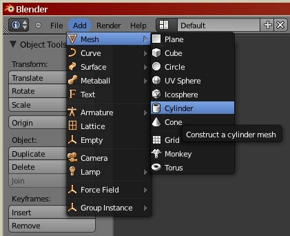
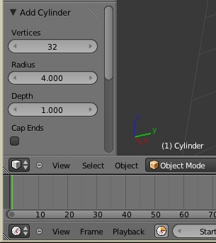
Add Mesh>CylinderCylinder Properties

Add a new cylinder mesh to the project, and set its properties to 32 verticies, radius 4, depth 1, uncapped.

Click for animated steps
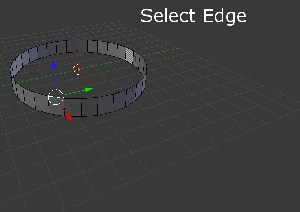
CTRL-TAB, E | Select edge select mode Blender tut edge select.jpg
RMB Right-click on one of the edges of the top-most ring.
CTRL-E, L Then use edge-loop to select all of the edges in the top ring.
E, S, SHIFT-Z, LMB extrude and scale x/y much smaller
E, G, Z, ., 5, Enter extrude and grab +z .5
E, S, SHIFT-Z, LMB extrude scale x/y a bit smaller
ALT-M, A Merge at center
Click for animated steps
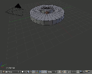
CTRL-TAB, F Change to face select mode Blender tut face select.jpg
SHIFT-RMB manually select alternate outside faces
E, S, 1, ., 2, Enter Extrude and scale by 1.2 times.
Individual Origins
Select Individual Origins for center of scale/rotation
S, ., 5, Enter scale end faces
Median Point
Warning.pngWarning:Do not forget to return the pivot point to Median Point.
A, G, Y, 1, 0, Enter select all, grab and move out of the way

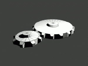
Repeat steps above with an uncapped cylinder of 16 sides, size 2, depth 1


RMB, CTRL-NUM+..etc.. Right click one face or edge in the large gear, and press CTRL-NUM+ repeatedly until all of the large gear is selected.

G, Y, LMB Move the large gear along the Y-axis until its teeth barely mesh with teeth of the smaller gear. Left-click to release the gear when its position is acceptable.

A, CTRL-N Select the entire mesh (both gears) and recalculate the 'Normals' so that all of the faces will be facing outwards.

Tab Switch to object mode Blender tut object mode.jpg

Object>Transform>Geometry to Origin

SAVE FILE as tut.blend

Unwrapping, UV Mapping, and Texturing

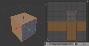
A typical unwrap of a simple cube.

Unwrapping can be challenging. While you can select to have Blender automatically unwrap your model, the results are usually a confusing mess of individual faces with no organization. Try to imagine how you would unfold the object if it were made of paper such as this unfolded cube.

Open a new windoid and set it to display the UVImage Editor so you can see the unwrapped results while you select edges to make seams.

Tab Select edit mode Blender tut edit mode.jpg
CTRL-TAB, E Select edge select mode
SHIFT-RMB Select edges to be made into seams.
CTRL-E, A Mark the selected edges as seams
A, U, U Select all and unwrap to see the layout int he UV editor windoid.

If your layout still looks like complete chaos, add/remove seams until the parts of the model can be easily identified.

These gears, and most mechanical items with lots of flat planes, are not too difficult to unwrap. Organic items, such as heads or animals are considerably more difficult.

Use G grab, and S scale to reposition and resize the UV islands in the UVImage Editor for optimal use of texture space.

export UV Layout as a 512x512 tut_uv.png

Note.pngNote: For purposes of this tutorial, the UV map we have just exported will be used as the texture. It is not very much to look at, but full texturing, Ambient Occlusion, Normal maps, etc.. are better handled in their own tutorials.
add material
name the material tut_uv (no need for filename extension)
add texture
Texture Type: Image of Movie
Open the tut_uv.png that we just exported
Mapping Coordinates: UV
center scene in camera and F12 to RENDER for a look
ESC to return 3D window

SAVE FILE

Rigging the Model

Tab Start in object mode Blender tut object mode.jpg
Set cursor to the origin
NUM3 Select view '3' Y/Z, looking down the X axis.
ADD > Armature > Single Bone This will create 'Armature Bone'
Tab Select edit mode Blender tut edit mode.jpg
Z Select wireframe visual mode (easier to position bones)
RMB Right click on the top end of 'Armature Bone' to select it
E, Z, 1, Enter This will extrude a new bone 'Armature Bone.000'
Deselect the 'Connected' checkbox to disconnect from its parent
G, Y, LMB Grab and center the bone over the big gear. This will its axis of rotation. Left-click to release the grab and accept its current location
G, Z, -, 1, Enter This will embed the bone into the gear (not necessary but cleaner)
RMB Right click on the original 'Armature Bone' to select it
E, Z, 1, Enter This will extrude new bone 'Armature Bone.001'
Deselect the 'Connected' checkbox to disconnect from its parent
G, Y, LMB Grab and center the bone over the smaller gear.
G, Z, -, 1, Enter Embed the bone into the gear (not necessary but ...)
Tab Switch back to object mode Blender tut object mode.jpg
RMB Right-click the mesh to select it
SHIFT-RMB Shift-right-click the armature
CTRL-P Parent the mesh to the armature with empty groups
Tab Return to edit mode Blender tut edit mode.jpg
RMB, CTRL-NUM+..etc.. Right click one face or edge in the large gear, and press CTRL-NUM+ repeatedly until all of the large gear is selected.
Under Object Data, set the vetex group as Bone.000 and click Assign
RMB, CTRL-NUM+..etc.. Right click one face or edge in the small gear, and press CTRL-NUM+ repeatedly until all of the small gear is selected.
Set vetex group as Bone.001 and click Assign

SAVE FILE

Lets check out our work...

Tab Select object mode Blender tut object mode.jpg
RMB Select bone.000 at the center of the large gear.
Blender should automatically switch to Pose Mode Blender tut object mode.jpg when the bone is selected.
R, Z, move mouse, RMB Only the large gear should spin in the z-axis, right-clicking RMB ignores changes
RMB Select bone.001 at the center of the small gear.
R, Z, move mouse, RMB Only the large gear should spin in the z-axis, right-clicking RMB ignores changes

Excellent!

Animating the Model

The large gear is going to spin in the opposite direction and at 1/2 the speed of the smaller gear. For sake of ease and sanity with rotating objects, set the animation stop at frame 360.

Animation Layout
Change screen layout from Default to Animation.
RMB Right click on the Armature to select it.
Tab To get to Pose mode if not already there. Blender tut pose mode.jpg
Active Keying
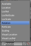
Set Active Keying to 'Rotation'

Large Gear Clockwise

Set frame counter to Frame 1
RMB Select bone.000
Blender tut set keyframe.jpg
Set a keyframe
Set Framecounter to Frame 91 (90 degrees +1)
R, Z, 9, 0, Blender tut set keyframe.jpg Rotate +90 degrees on the Z-axis and set a ROT keyframe.
Set Framecounter to Frame 181 (180 degrees +1)
R, Z, 9, 0, Blender tut set keyframe.jpg Rotate +90 degrees on the Z-axis and set a ROT keyframe.
Set Framecounter to Frame 271 (270 degrees +1)
R, Z, 9, 0, Blender tut set keyframe.jpg Rotate +90 degrees on the Z-axis and set a ROT keyframe.
Set Framecounter to Frame 361 (360 degrees +1)
R, Z, 9, 0, Blender tut set keyframe.jpg Rotate +90 degrees on the Z-axis and set a ROT keyframe.

Small Gear Counterclockwise

Set frame counter to Frame 1
RMB Select bone.001
Blender tut set keyframe.jpg
Set a keyframe
Set Framecounter to Frame 91 (90 degrees +1)
R, Z, -, 9, 0, Blender tut set keyframe.jpg Rotate -90 degrees on the Z-axis and set a ROT keyframe.
Set Framecounter to Frame 181 (180 degrees +1)
R, Z, -, 9, 0, Blender tut set keyframe.jpg Rotate -90 degrees on the Z-axis and set a ROT keyframe.
Set Framecounter to Frame 271 (270 degrees +1)
R, Z, -, 9, 0, Blender tut set keyframe.jpg Rotate -90 degrees on the Z-axis and set a ROT keyframe.
Set Framecounter to Frame 361 (360 degrees +1)
R, Z, -, 9, 0, Blender tut set keyframe.jpg Rotate -90 degrees on the Z-axis and set a ROT keyframe.

SAVE FILE

But wait! The smaller gear should spin twice as fast!

Click to see animated results.

Uncheck all of the keyframes for Bone.001

Select Bone.002
RMB Right-click to select one of its f-curves
A, CTRL-C Select all and copy the keyframes
Move framecounter to 362
CTRL-V Paste the copy of those keyframes after the existing frames.
A, S, X, ., 5, Enter Select all and scale the X axis by .5
G, X, -, 1, 8, 0, Enter Grab shift the f-curve 180 degrees to the right.
Return framecounter to Frame 1
Object mode Blender tut object mode.jpg
Play animation.

SAVE FILE

Getting the Model into Source

Exporting

Tab Make sure Blender is in Object mode. Blender tut object mode.jpg
RMB Right click on the mesh (the gears)
SHIFT-RMB The shift-right-click on the Armature
File->Export->SMD->selected

Voom.

Exit Blender

Note.pngNote:These examples use a command line executing text editor, {ConText}, to compile QC files. This saves on lots of repetitive typing of long directory trees into a console command line. Interlopers has a well designed and easy to follow tutorial on the setting up ConText for compiling models via their QC file. See: External Links

QC, File Names, and File Locations

Correct file paths and naming is probably the cause of the majority of failures in compiling QC files.

Models :: Materials :: SMD ::

My model compiles, but the texture doesnt show up!? My model is invisible!?

Example:: QC FILE SMD FILE File Locations

Compiling and Viewing

See Also

External Links

{Interlopers -- QC Compiling Tutorial using ConText}

--Tehrasha 22:54, 18 April 2011 (UTC)