Half-Life: Alyx Workshop Tools/Modeling/LODs
This tutorial demonstrates building a model with multiple levels of detail (LODs). This tutorial uses primitive shapes as an example, but references to mesh files (.fbx, .dmx) can be directly substituted.
Create the highest detail level
In this example we will create a sphere with 3 levels of detail. To do this we will first add all 3 versions of the sphere to the render mesh list.
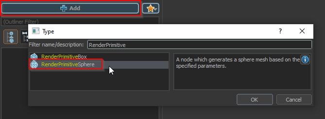
Click the Add node button and select the 'RenderPrimitiveSphere' node type.
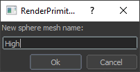
When prompted for a name, give this sphere the name 'High'.
This sphere will represent the highest level of detail.
When prompted to select a bone, select 'none'.
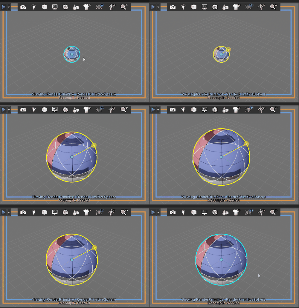
Adjust the radius of the sphere to be 32 units by left clicking and dragging the manipulator ring that appears around the outside of the sphere.
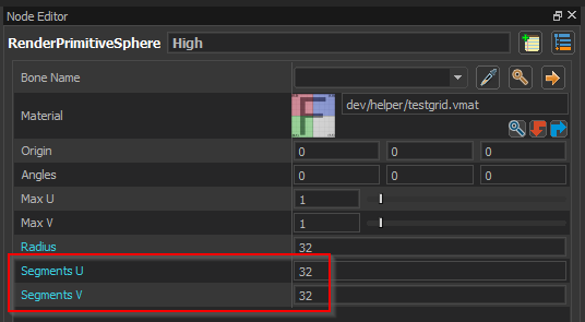
Use the Node Editor to make the sphere more smooth by setting the Segments U and Segments V properties to 32.
Create the lower detail levels
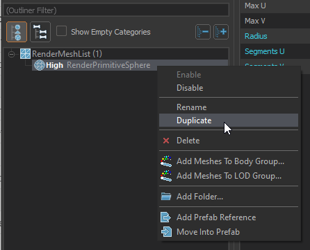
Duplicate the high detail level sphere by right clicking on the RenderMeshList in the Document Outliner and then selecting Duplicate from the context menu.
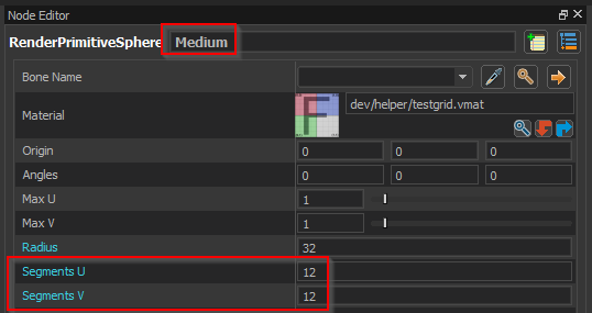
Use the name field at the top of the Node Editor to rename the new duplicate sphere to 'Medium', then set the Segments U and Segments V to 12.
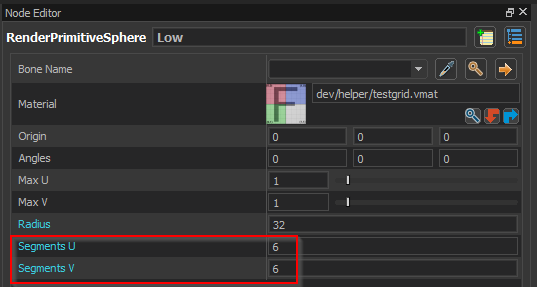
Duplicate the high detail level sphere again, this time renaming the copy to 'Low' and set the Segments U and Segments V to 6.
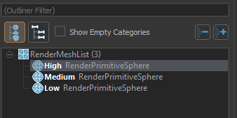
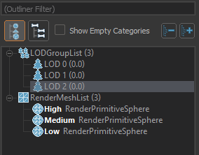
You should now have all 3 spheres under the RenderMeshList in the Document Outliner.
Add an LOD group for the highest detail level
If you compile the model at this point all 3 spheres will be visible all the time, although it will be hard to tell since they are on top of each other.
We can change the model to only have a single version of the sphere visible at a any given time by adding LOD groups. LOD groups specify which mesh or meshes are visible at each level of detail.
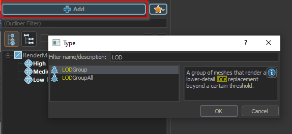
Click the Add node button and select the 'LODGroup' node type.
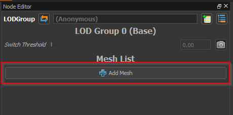
With the new LOD Group node selected, click the Add Mesh button in the Node Editor.
This will add an empty mesh selection field in the ui.
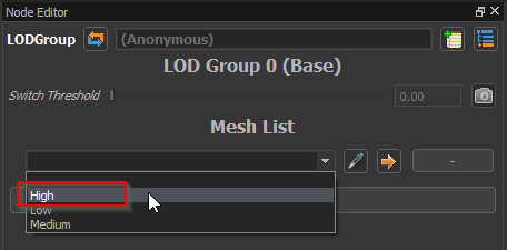
Click the drop-down on the empty mesh selection field and select the 'High' mesh from from the list.
This will add the sphere named 'High' to the list of meshes included in LOD Group 0. LOD group 0 represents the highest level of detail and is visible by default.
Add lower level LOD groups
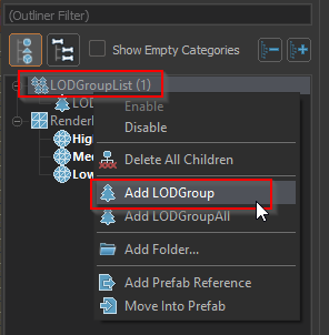
Right click on the LODGroupList in the Document Outliner and select Add LODGroup.
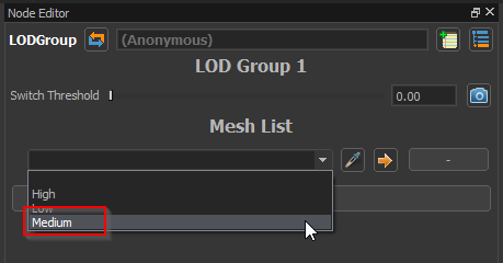
As before, click the Add Mesh button to add an empty mesh selection field, then click the drop-down and select the 'Medium' sphere.
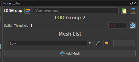
Repeat the above two steps to add an additional LOD Group and add the 'Low' sphere to the group.
You should now have 3 LOD Groups in the LODGroupList in the Document Outliner.
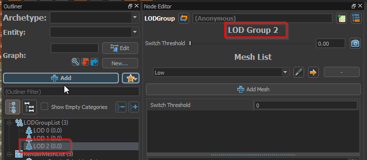
If you select each one of the groups in the outlienr you should see that LOD 0 references the 'High' sphere, LOD1 references the 'Medium' sphere and LOD2 references the 'Low' sphere.
Set the LOD switch distances
The model now has 3 LOD levels defined, but we still need to specified the distance at which each LOD should be active.
Click the Needs Compiling button to save and compile the model.
You can now preview each of the LOD levels explicitly by selecting one from the LOD drop-down in the top toolbar
Select LOD 2 from the toolbar drop-down, then also select LOD 2 in the Document Outliner, so that the Node Editor is displaying the properties for LOD Group 2.
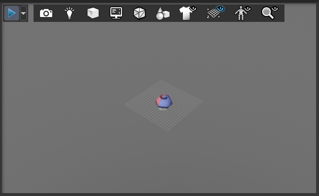
Zoom out in the 3D viewport (Alt + Right Mouse) until the low detail sphere is small enough that it is of acceptable quality.
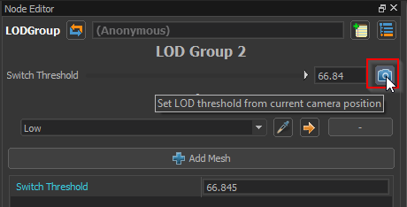
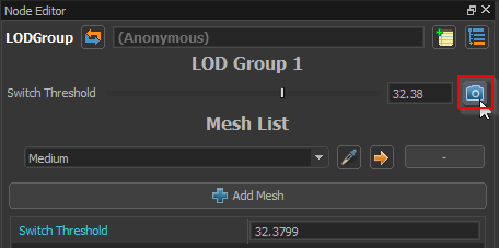
Click on the camera button in the Node Editor to set the Switch Threshold based on the current view in the 3D Viewport.
You should see the value of the Switch Threshold property change when you click the camera button.
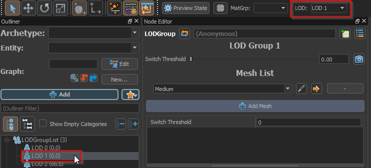
Select LOD 1 from the toolbar drop-down and select LOD 1 in the Document Outliner so that the 3D viewport is previewing LOD 1 and the Node Editor is displaying the properties for LOD Group 1.
Adjust the zoom of the 3D viewport to the point where the quality of the visible 'Medium' sphere is just acceptable, then click on the camera button in the Node Editor..
Note that the Switch Threshold value is set. This value should be smaller than the value that was set for LOD 2 in the previous step.
Save and compile the model by clicking on the Needs Compiling button.
Preview the LODs
Re-enable automatic LOD selection in the 3D viewport by selecting Auto LOD from the toolbar's LOD selection drop-down.
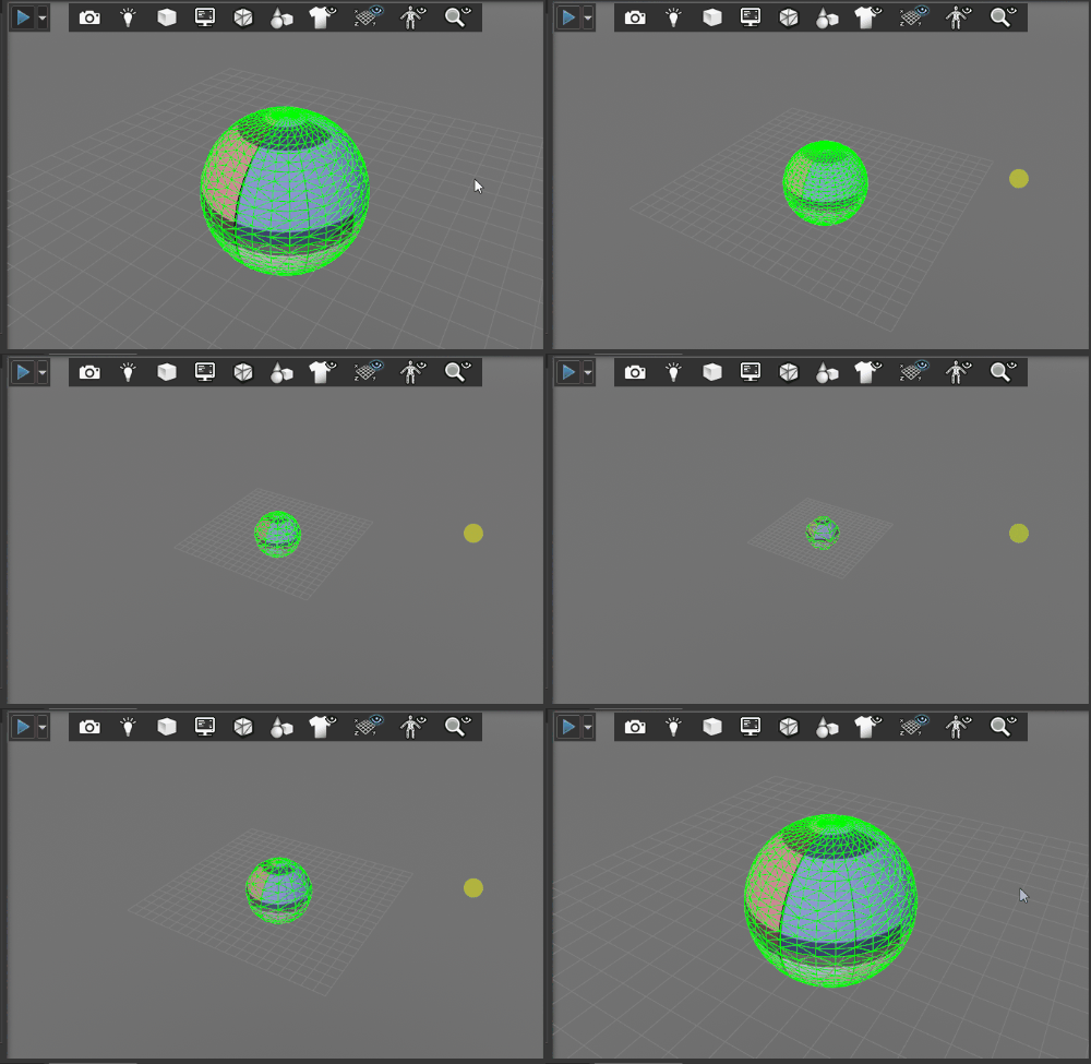
This causes the editor's 3D viewport to pick the lod based on the size of the model in the viewport in the same way that the game will.
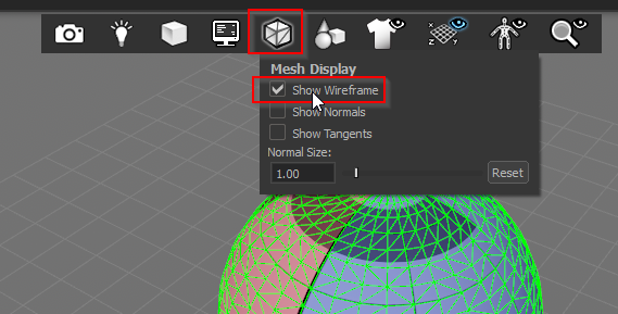
Enable wireframe preview from the 3D viewport toolbar by selecting Show Wireframe.
This will make it easier to see the changes in the LOD level to verify that the LODs are working as expected.
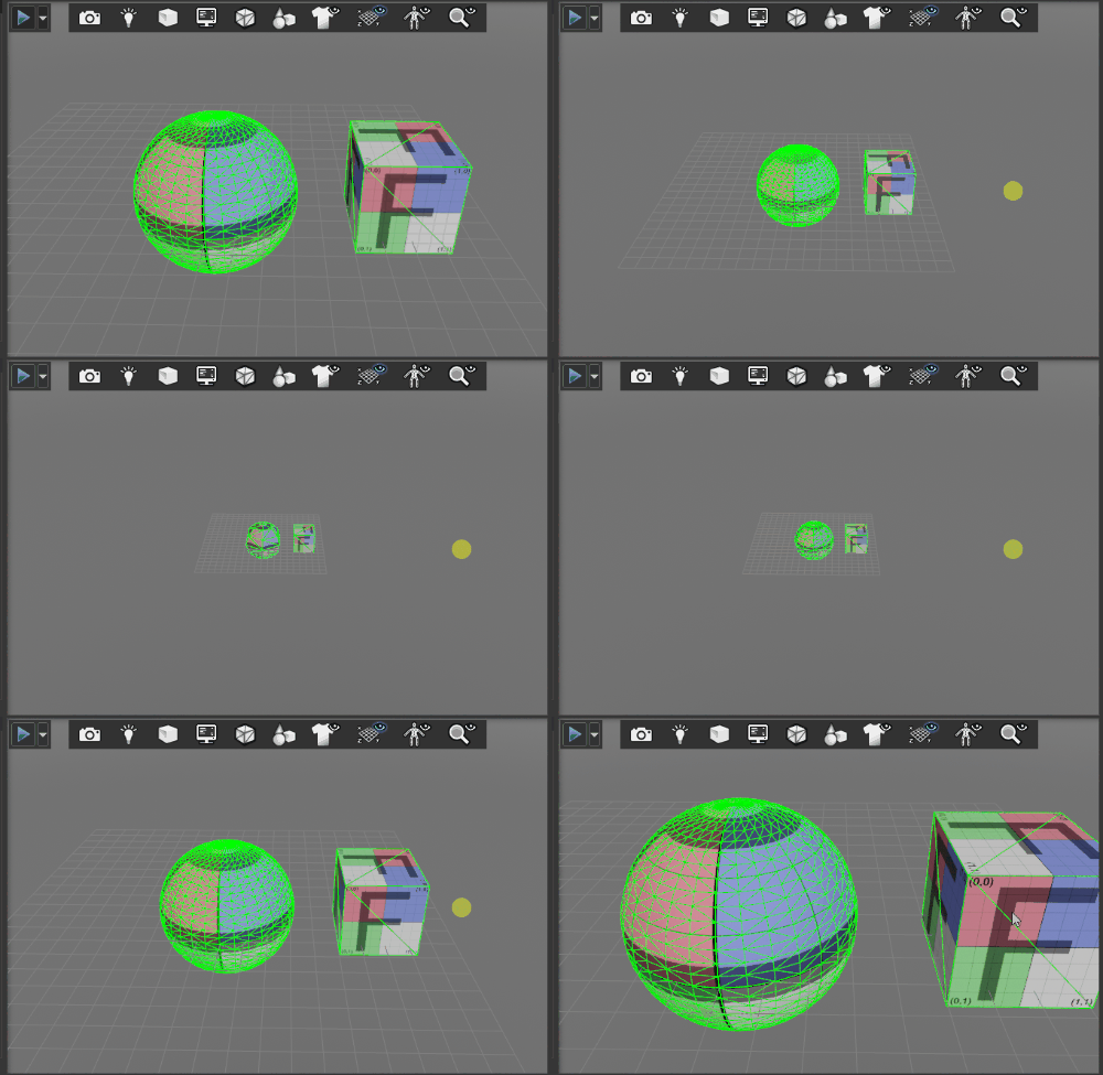
Zoom in and out in the 3D view. If you have enabled the Auto LOD mode, you should be able to see the visible meshes switching based on your zoom level..
Add a mesh which does not have LODs
In some cases you may want a mesh be visible in all LOD levels. While it is possible to accomplish this by adding the mesh to each and every LOD Group, it can also by achieved by using the LOD Group All.
We will create a single box which will be visible in all LOD levels to demonstrate this.
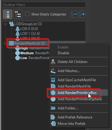
Create a box primitive by right clicking on the RenderMeshList in the Document Outliner and selecting Add RenderPrimitiveBox.
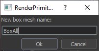
Name the box 'BoxAll' and select 'none' for the parent bone .
In the 3D viewport change the model display mode to Always so that you can see the sphere while editing the box.
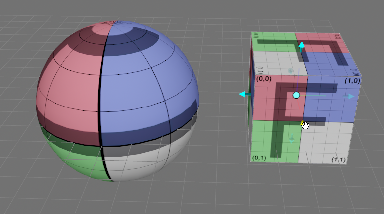
Use the manipulator handles to move and resize the box so that it is next to the sphere instead of inside it.
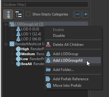
Add the all levels LOD group by right clicking on the LODGroupList in the Document Outliner and selecting Add LODGroupALL.
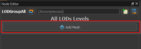
With the new All LOD Levels group selected in the Document Outliner, click the Add Mesh button in the Node Editor.
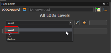
Select the 'BoxAll' mesh from the empty drop-down.
Click the Needs Compiling button to save and compile the model.
You should now be able to zoom in and out in the 3D viewport and see the sphere swapping between meshes while the box is always visible.
