Half-Life: Alyx Workshop Tools/Modeling/Jointed Physics Prop
This tutorial demonstrates creating a simple jointed physics prop. A jointed physics prop is a model with two or more physics bodies that are connected by a joint (constraint). This can also be considered a simple form of a ragdoll.
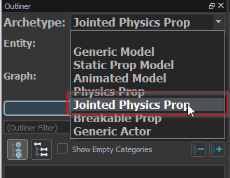
Select the Jointed Physics Prop archetype
Create a new document and from the Document Outliner archetype drop-down, select Jointed Physics Prop
Create the render meshes
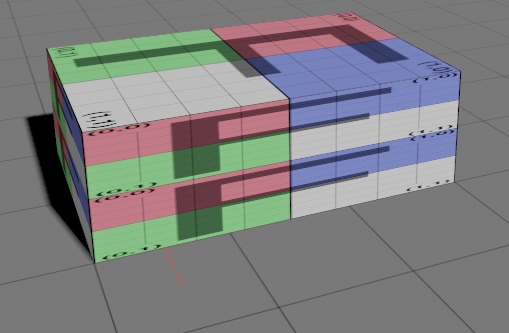
In this example we are going to create a simple two part hinged box, for this purpose we will need two separate boxes.
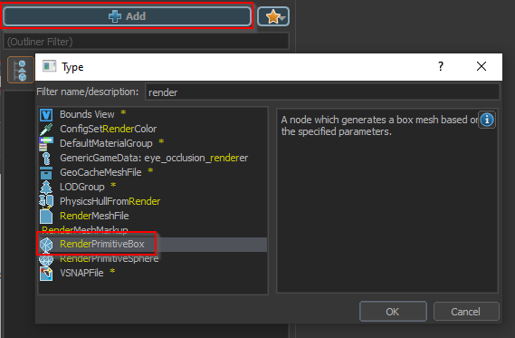
Click the Add node button and select the 'RenderPrimitiveBox' node type.
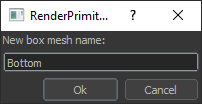
Name the new box 'Bottom' and select 'None' when prompted for a parent bone.
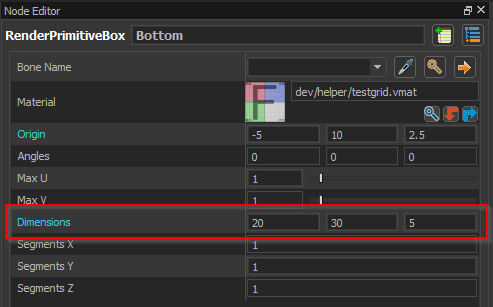
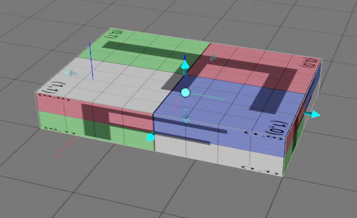
Using the Node Editor or the manipulator handles in the viewport, adjust the box dimensions to be 20 x 30 x 5.
Now we want to stack an identical box on top of this box. Instead of creating a new box, we can simply copy this box.
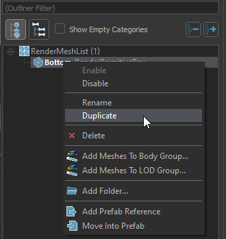
In the Document Outliner select the 'Bottom' mesh, right click on it and from the context menu select the Duplicate command.
Alternatively, with the 'Bottom' mesh selected, you can press Ctrl+C to copy it, and Ctrl+V to paste it.
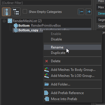
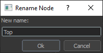
Rename the new mesh to 'Top' by right clicking on it and selecting Rename from the context menu.
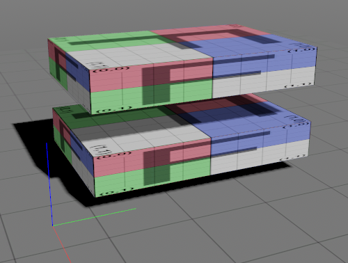
You will now have two identical boxes. However, it will be hard to tell there are two in the viewport since they are in the exact same location.
Reposition the top mesh
In order to make positioning the top mesh easier we will want to see the location of the bottom mesh while we are editing the top mesh. The default behavior is that selecting a mesh hides the rest of the model. In this case we would rather continue to see the whole model while the mesh is selected.
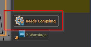
First, click the 'Needs Compiling' button to compile your model.
If you have not yet saved your model, this will prompt you to choose a filename and save.
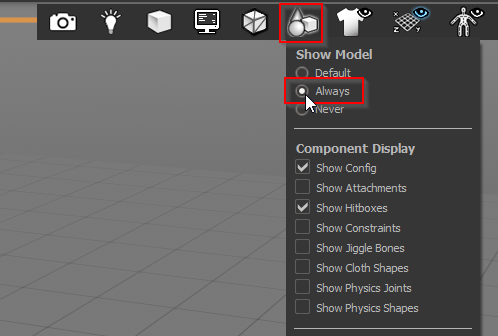
From the Viewport Tool Bar select the component display menu and select the Always option under Show Model.
With the 'Top' mesh selected, click on the translate tool.
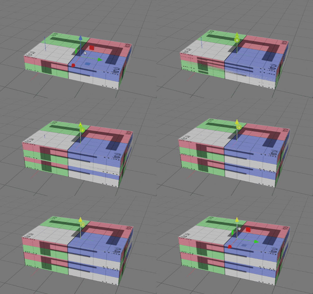
Left click on the translation tool gizmo and drag it upwards to move the 'Top' box up.
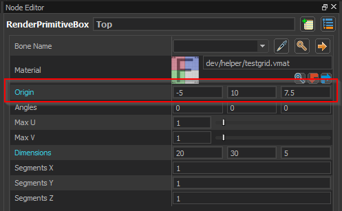
Alternatively you can type in an exact value for the origin in the Node Editor
Click the Needs Compiling button again to update the model with the new position of the box.
Create the physics shapes
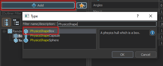
Click the Add node button and select the 'PhysicsShapeBox' node type.
When prompted for a bone, select none.
We want the physics box to match the bottom rendering box. While we could manually adjust it to the same position and size, it is easier to just copy the values.
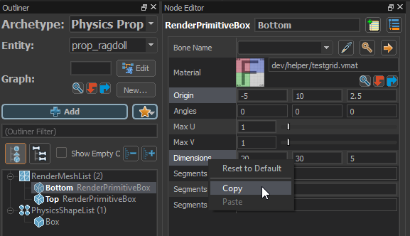
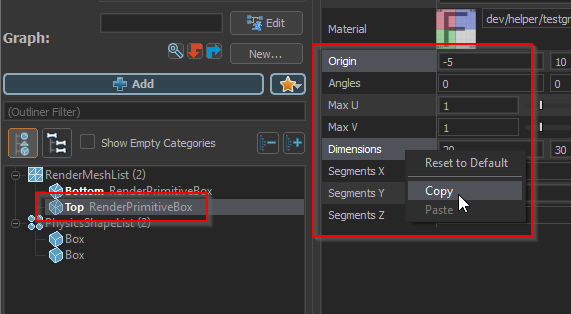
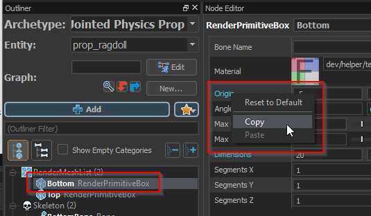
Select the 'Bottom' render mesh in the Document Outliner, then from the Node Editor select both the Origin and Dimensions properties by holding Ctrl and Left Clicking on both.
Then Right Click and select Copy from the context menu.
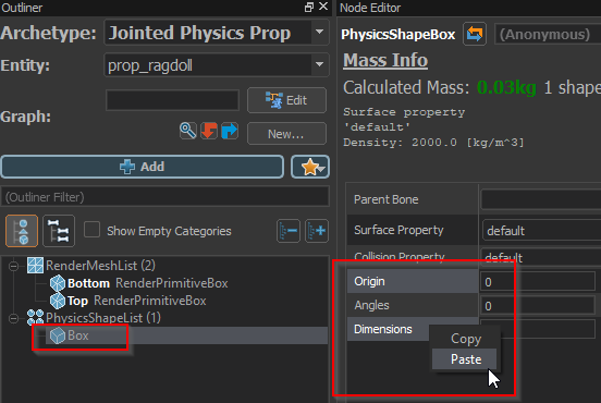
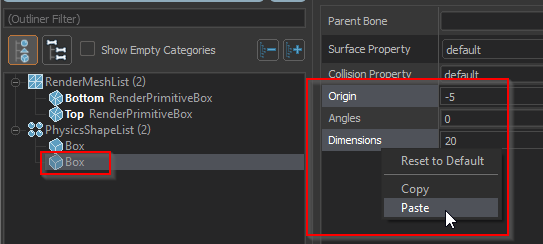
Select the physics box in the Document Outliner, then from the Node Editor select its Origin and Dimensions using Ctrl + Left Click.
Then Right Click and select Paste from the context menu.
This box should now exactly match the size and position of the bottom render box.
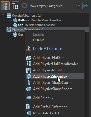
Now add another physics box by Right Clicking on the PhysicsShapeList and selecting Add PhysicsShapeBox.
This time select the 'Top' render mesh and copy its Origin and Dimensions.
Select the second physics box and paste the Origin and Dimensions from the 'Top' render mesh on to it.
Test the physics behavior
Now that we have created the physics shapes, we can test the physics behavior
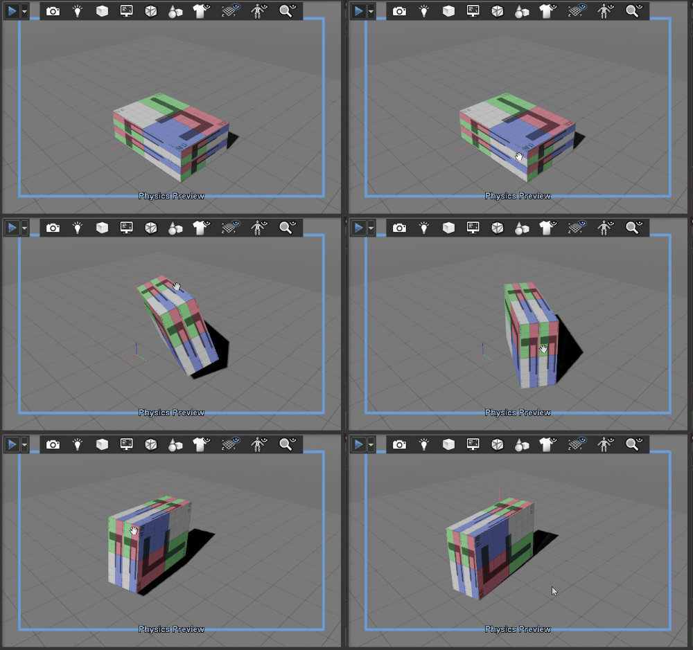
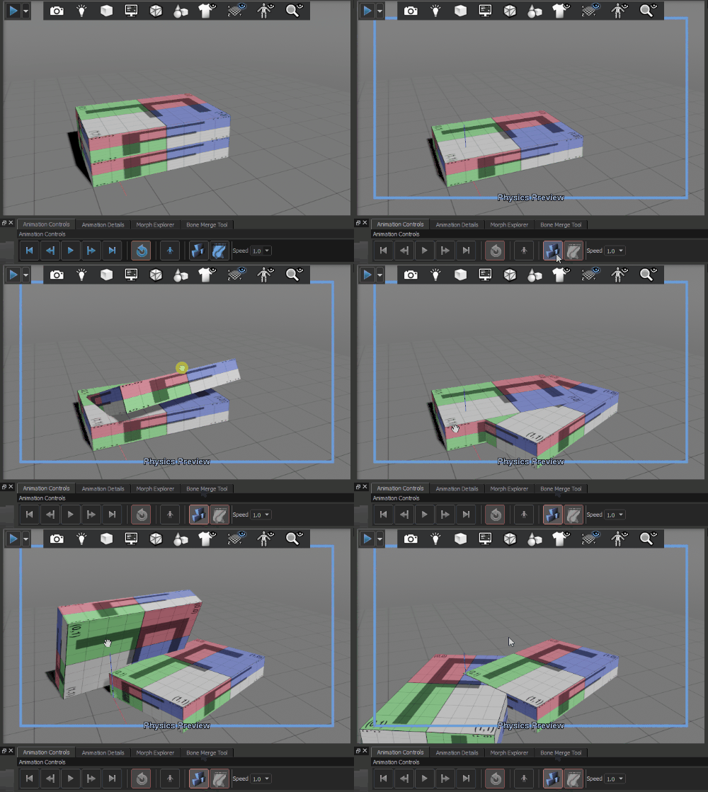
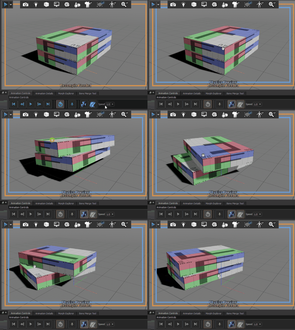
Click on the Toggle Physics Sim button in the Animation Controls.
Grab and drag the box in the 3D viewport by Left Clicking on the box and moving the mouse while holding the left button down.
Note that despite having being constructed from two separate boxes, it simulates as a single solid box. This is because there are no bones in the model and all physics shapes are assigned to a single physics body. To generate multiple physics bodies, the model must have bones.
Add bones to the model
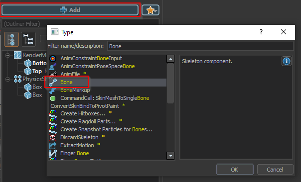
Click the Add node button and select the 'Bone' node type.
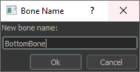
Name this bone 'BottomBone'.
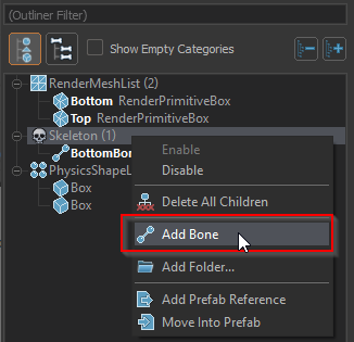
Add a second bone to the model by Right clicking on the Skeleton node in the Document Outliner and selecting Add Bone.
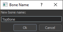
Name this bone 'TopBone'.
Attach the boxes to the bones
We now want to attach both the render meshes and the physics shapes to the bones
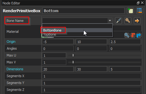
Select the 'Bottom' render mesh in the Document Outliner and the in the Node Editor select 'BottomBone' from the Bone Name drop down.
Repeat this process, selecting the 'TopBone' for the 'Top' render mesh.
Then select each of the boxes in the physics shape list and assign them to the 'BottomBone' and 'TopBone' as well..
Since the physics boxes are not named, you may need to look at the 3D viewport to see which one you have selected to ensure you assign them to the correct bone.
Right now both bones are on top of each other at the origin. It will be easier to setup joints if they are at the origin of each box.
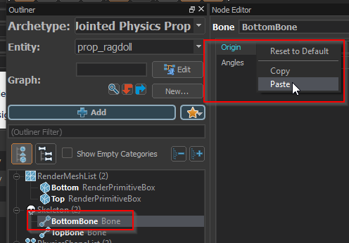
Select the 'Bottom' render mesh and copy its origin value.
Paste the value on to the origin of the 'BottomBone'.
Repeat the last two steps to copy the value of the origin from the 'Top' render mesh to the 'TopBone'.
Click the Needs Compiling button to compile and update the model with the new bone positions.
Note that the boxes have moved and are no longer directly on top of each other. This is because their position is relative to their parent bone. Since we moved the bone origins, we actually need to reset the origin value of the boxes themselves.
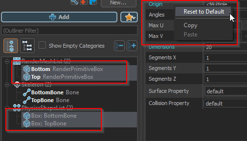
Select both render meshes and both physics boxes in the Document Outliner by holding the Ctrl key while left clicking on them..
Then right click on the Origin property and select Reset to Default.
After re-compiling the model again, everything should be in the correct location.
Re-test the physics behavior
Click on the Toggle Physics Sim button in the Animation Controls.
You can see that the boxes now behave completely independently. In the next section we will create a joint to link them together.
Create a physics joint
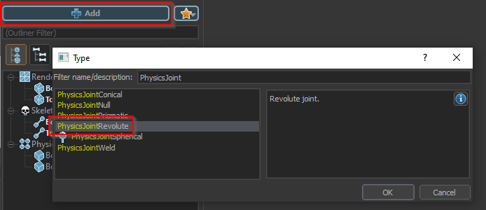
Click the Add node button and then select the 'PhysicsJointRevolute' node type to create a hinge style joint.
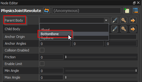
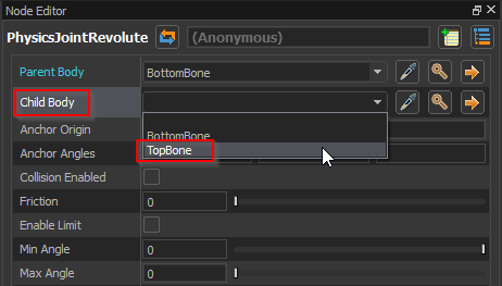
With the new joint selected, find the Parent Body drop-down and select the 'BottomBone'.
Then select the 'TopBone' from the Child Body drop-down.
Run the physics simulation again. You will see that the boxes are now connected, but not in the way we want..
Adjust the joint parameters
We want the joint to make the boxes behave like they are connected by a hinge. To do this we need to move the joint to where we want the pivot of the hinge to be located and we need to set some limits on the range of motion.
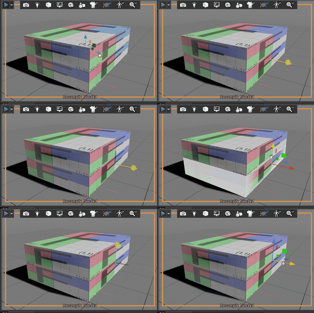
Select the Translate tool from the tool bar..
With the physics joint selected, use the manipulator to move the origin of the joint to be aligned with the center of one side of the box.
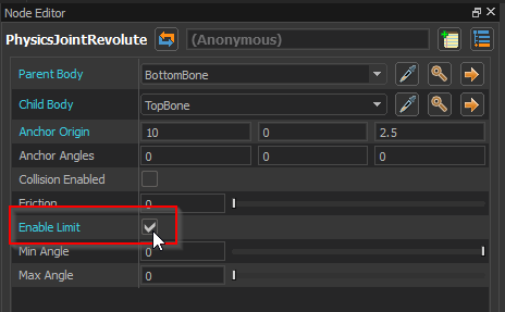
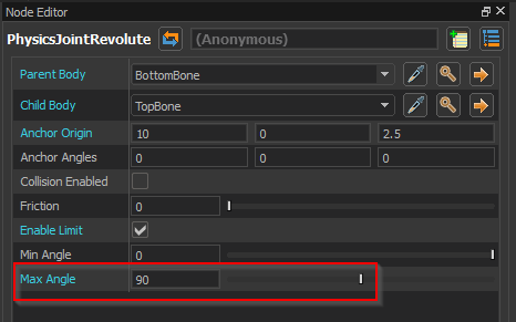
Enable limits on the joint by clicking on the Enable Limit checkbox in the Node Editor.
Set a maximum angle of 90 so that the joint will allow a 90 degree range of rotation.
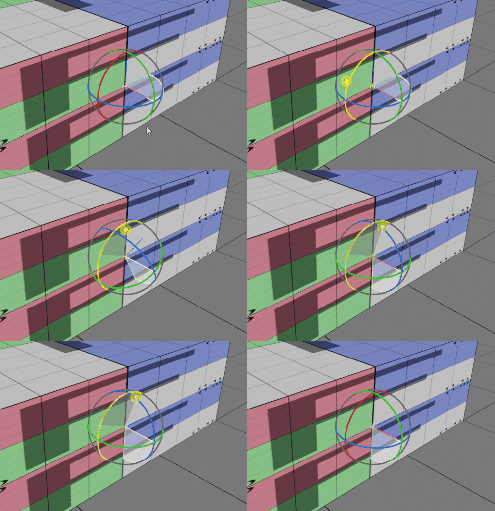
Note that the range of motion is displayed by white arc. It is not currently aligned with the axis we want the hinge to be on, so we must rotate the joint
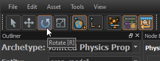
Select the Rotate tool from the toolbar.
With the physics joint selected, use the Rotation manipulator to rotate the joint 90 degrees so that the swing angle is vertical instead of horizontal.
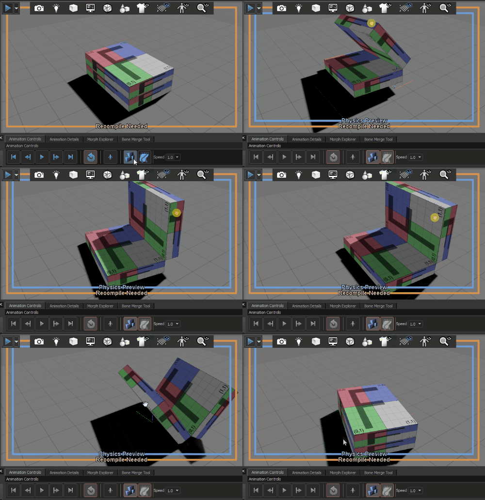
Run the physics simulation again. The model should now behave as if the boxes are connected by a hinge allowing a 90 degree range of motion..
Add prop data
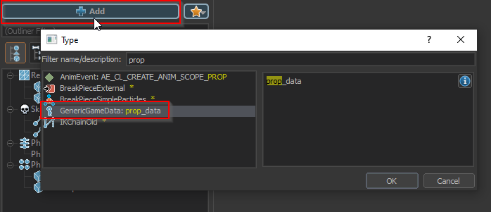
All physics props must have prop_data to function in game.
Click the Add node button and select GenericGameData: prop_data.
The prop_data can be used to change how the model responds to being damaged. In this case the defaults are fine and we don't need to set any values.
Test the model in game
Click the Needs Compiling button to compile the model.
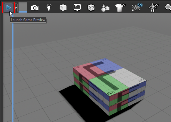
Click the Launch Game Preview button in the upper left corner of the 3D viewport to start the game preview mode
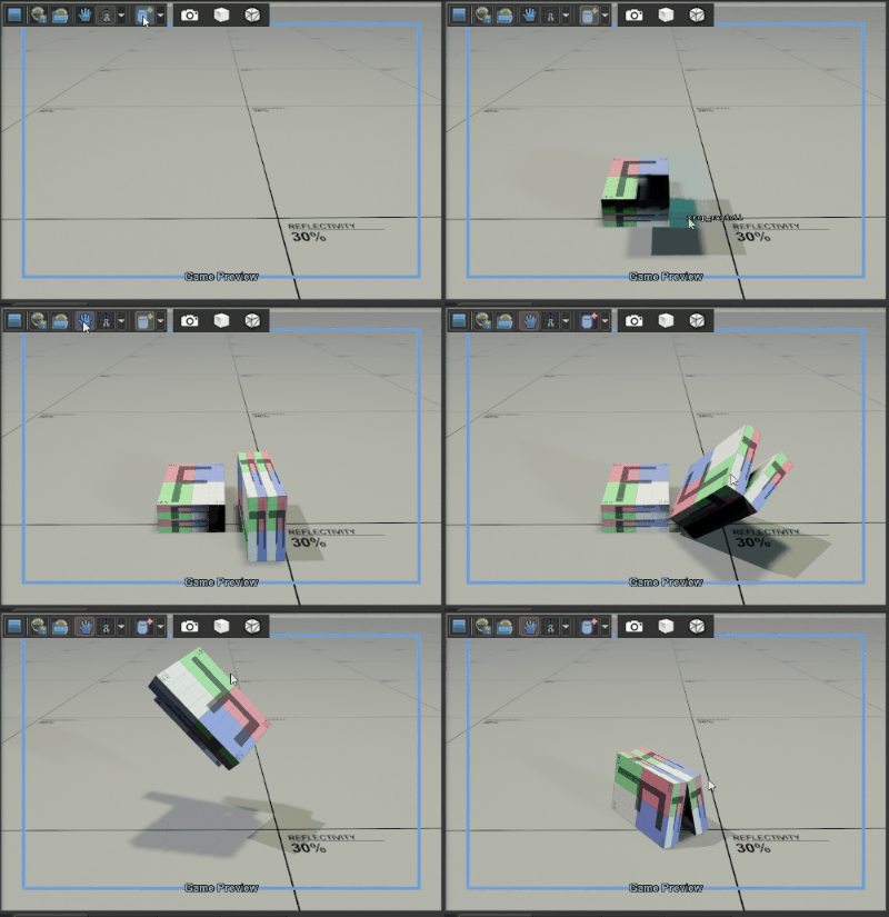
Use the Spawn tool to place one or more instances of the box and use the Grab tool to move them around to verify that the hinge works correctly.
