Binary space partitioning
BSP stands for Binary Space Partitioning. .bsp is the file extension for maps/levels used by many BSP based game engines. For more information how BSP works see the Wikipedia article on binary space partitioning.
What is "BSP" in the first place?
To understand what binary space partitioning is, break down the word into its pieces: Partitioning, or separation, binary, or two, as in two-sided, and space, or existential area. Basically, binary space partitioning means cutting up space into sides, and every part of the world is on a side of some partition, or divider.
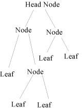
Most game engines these days use a BSP tree, which is a simple two-child tree structure. To understand what this means, one must first be familiar with the tree structure in programming. Basically, a two-child tree looks something like this:
Now, that obviously looks nothing like the world you see when you play, but that's how it appears to the engine. Basically, the head node contains everything in the entire world, and each node in turn has children. Some nodes have no children, which means they're called "leafs", just like leafs on a tree have no branches.
How does this have anything to do with the 3D world?
Each node (and leaf) branching off from a node higher up in the tree is separated by a plane, which is basically a flat invisible sheet in the world. Which side a point is on the side of that plane determines which way you search the tree when trying to find your location.
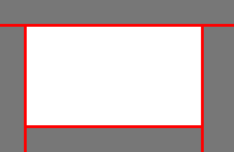
To better explain it, I'll make some diagrams representing a 2D world, using lines instead of planes. In these diagrams, white space represents empty space, gray represents solid space, and red lines represent BSP partitions.
This is a simple, 4-sided room, with solid world outside. Now, there are 5 different places you could be in the world given that diagram, so those areas are the leafs in the tree diagram. Basically, within each leaf , there are no lines left to separate your location. However, a 4-sided room is kind of useless in the world of BSP, so let's add something to make it useful: A block. And that brings us to our next section:
What's CSG mean and how is the BSP tree useful for location finding?
CSG is an acronym for Constructive Solid Geometry. To understand it, once again, it's best to dissect the term. Constructive, meaning used to put together something more complex, solid, meaning an obstruction (in this case), and geometry, which means a mathematically-defined shape. Basically, constructive solid geometry is geometry used to construct a larger solid piece of geometry. There are also "CSG operations", which are mathematical algorithms used on CSG pieces (commonly called brushes) to cause brushes to interact with each other and the world.
Important CSG operations include merging, subtracting, and cutting (a form of subtraction used in the BSP tree generation process).
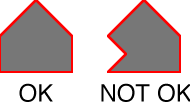
In most editors now a days, a basic CSG unit is called a "brush", which is used to describe a single convex solid. Remember, it has to be convex. In other words, geometry with dents and such in it are not allowed.
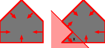
The reason for this is that the second brush isn't a convex solid. In order for the engine to find out which leaf a point is in, that leaf has to be completely enclosed, and for many reasons, CSG operations won't work unless the same is true for the brushes. Take a look at the diagram below.
The X marks a location which is behind one of the partitions, which means it could be considered outside of the brush, even though it's actually inside.
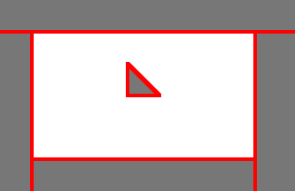
So, let's see what happens when a simple wedge is added to the example room:
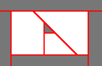
Unfortunately, this can't be done as-is, because the empty space needs to be sectioned off, divided only by partitions with nothing else inside it. So, to do this, a CSG subtraction of the empty space is done, generating partitions along the lines of the added brush.
How does a BSP tree get generated from this?
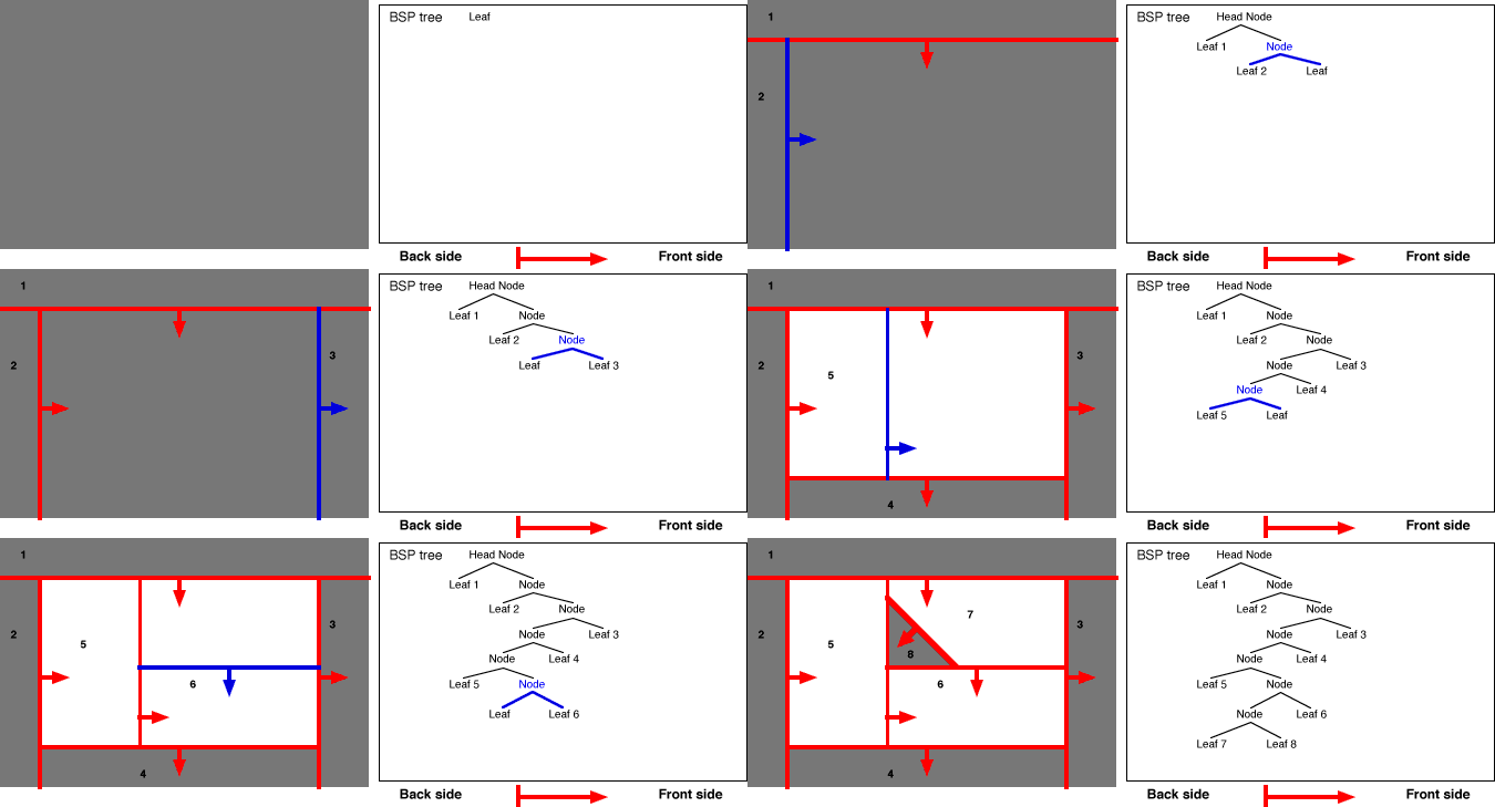
Basically, a BSP tree is created by adding each partition to the tree one at a time. To reduce the number of cuts in the CSG operation, axial partitions, as in lines that only go horizontally or vertically, or in the 3D world, walls, floors, and other non-angled objects, are added first. Each time a partition is added, one of the leafs is split into a node, divided by the partition, eventually creating a finalized tree!
It's important to realize that any leaf can be split into a node, not just ones just created. If a wedge was added to Leaf 6, for example, Leaf 6 would become a node and be split into more leafs.
How are BSP trees used for collision detection?
Well, the basic type of collision detection is line collision. Line collision just means a line is traced through the world until it hits something, or reaches its end point.
So how is the BSP tree used for this? Basically, by recursively checking leafs one-by-one starting from the start point and moving to the end. If one of the solid leafs has the line in it, then it's a hit. If not, it's a miss.
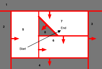
Let's take a look at the picture below:
In this picture, a line is being traced from a point in leaf 5 to leaf 7, passing through leafs 8 and 6.
So here's the method for determining which leafs the trace line is passing through and in which order:
Start
Make the head node the current node.
Side check
If both the start and end of the trace line are on the same side of the current node's partition, then it means it doesn't cross over the partition, so no collision with any part of one side could be possible. The only possible collisions are ones that could occur on the side both are on, so mark the current node as "MISS", make the child that both the start and end are on the current node, and start step 2 over.
If the start and end are on different sides of the partition, then it means it crossed a node partition, so it might have collided with something. This needs to be checked, so move to step 3.
Split check
Step 3 is only reached if the trace line is split by a node partition. Since we're only interested in the first solid object (or leaf) the trace hits, the side the start point is on should be checked first. So, go down the tree on the side the start point is on, and do step 4. If that side's clear, then go down the side of the tree that the end point is on, and do step 4 there. If both sides checked out on step 4 and neither hit anything, then the trace didn't hit anything in the current node. Mark it off as "MISS" and go back up the tree from the current node. If you can't go up the tree any further, then the trace is done: It's either a hit or miss.
Recursion or contents check
Now, a single side of a partition is being checked to see if the line hits there.
If the side being checked is a leaf, then it means one side of the split check is done: If the leaf is empty, then the trace didn't hit on the side of the partition currently being checked, in which case mark the leaf as "MISS", go back up the tree, and back to step 3. If the leaf is solid, it hit, so mark the leaf as a "HIT", and mark the node above as a "HIT" too, then go back up the tree.
If the node being checked is not a leaf, then it has to be checked the same way the first one (the head node) was. So, make the node being checked the current node, and go to step 2.
For anyone who's not a programmer, this may be a bit confusing. For anyone who is, here's a pseudo-program for determining it:
checknode (currentnode)
   if(currentnode is a leaf)
       if(currentnode contents are solid)
           return HIT
       else
           return MISS
   if(side start is on = side end is on)
       return checknode (child of currentnode both sides are on)
   result1 = checknode (child of currentnode start is on)
   result2 = checknode (child of currentnode end is on)
   if(result1 does not equal result2)
       nodehit = currentnode
   if(result1 = HIT or result2 = HIT)
       return HIT
   else
       return MISS
How do I determine which partition the line hit, since its angle can be used for stuff like deflections?
Basically, the highest node up on the tree where one side's got at least one hit and the other are all misses is the one whose partition the hit is on!
How are BSP trees used for sorted rendering?
Since only leafs should have parts of them drawn, you can always find the most distant leafs from the player by recursing the tree and instead of picking the side the player is on, pick the side they're NOT on. This won't give you the leaf with the most space between them, but it will give you the one with the most leafs between it and the player! After a leaf has been rendered, just go back up the tree one step, go down the other child, and start over, until the entire tree has been rendered!
What are clipping hulls?
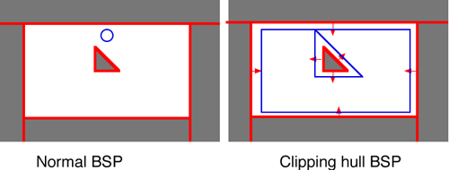
I already showed how BSP trees are useful for line traces, but those are only useful for simulating tiny objects like bullets. For larger objects, there are many ways to do collision, one of the first being using clipping hulls. Basically, the idea behind a clipping hull is to make a collision check for a large object be done the same as a small object by creating a separate BSP tree with the walls caved in. In brush-based environments, this is easily achieved by just pushing the partitions of every brush outward, then rebuilding the BSP, then just tracing the center of the object through the new "hull".
You may notice a problem with this though: Even though the walls have all been moved out the same distance, the player can no longer get past the block if he goes to the top of the map. This brings us to the next question:
What are axial planes?
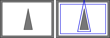
Axial planes are partitions added to prevent blockages like the one shown above from occurring. To make the problem more obvious, take this example:
As you can see, the gap between the walls and the wedge are about the same, which means there should be a gap on both the top and bottom of the clipping hull, except there isn't. Even though the walls have been pushed out the same distance, the top edge is more acute, which makes it push out farther. There are several ways to solve this, but the easiest is to add axial planes, which in the 2D world go only horizontal and vertical, and in the 3D world are non-angled planes like walls and ceilings.
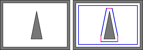
Here's what happens when axial planes are added to the brush:
As you can see, there is now a gap at both the top and bottom, so the player could safely travel across both sides of the wedge.
How is visibility determined in Quake-based engines?
Even though it takes a long time, the way visibility is determined is actually pretty simple.
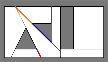
Take this semi-complex BSP below:
One of the things done during the BSP process in all Quake-based engines is portalization. During portalization, every separation of every leaf is converted into a portal. Ones that are opaque, such as wall surfaces and water in some engines, are considered opaque portals. Others are just used to determine visibility from the boundary areas of a leaf.
The way Quake's visibility processing works is by trying to create a "separating plane" for each pair of portals, which is basically a sheet or line that would put two portals on one side, and a third portal on the other. If that can be done, then the portal left standing alone is considered not in the way. If it happens, however, then that portal is considered in the way, which means the two portals can't see each other.
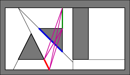
Here's approximately what would happen if the red portal was VIS'ed against the green portal:
As you can see from the magenta lines, there is no line that can be drawn separating the blue portal from the green one, so the blue portal is considered in the way.
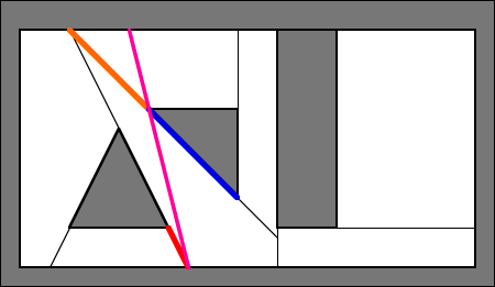
When the orange portal is put against the red portal, however, it's different:
The magenta line shown completely clips away the blue portal, while leaving the red and orange portals on the other side. This means that the blue portal is not in the way, and if no portals are in the way, then the red and orange portals can see each other.
What are detail brushes?
Detail brushes are something introduced in ![]() Quake II, and seen in many other engines. They have also been implemented in modern compilers for
Quake II, and seen in many other engines. They have also been implemented in modern compilers for ![]() Quake and
Quake and ![]() GoldSrc.
Detail brushes essentially aren't included in the portal list when it's exported by the BSP utility, which means there's no way they can get in the way during the visibility process. However, in order for that to be truly effective, a "cluster" visibility system is needed. In a cluster system, instead of the visibility data telling the engine which leafs can see each other, it tells the engine which sets of leafs can see each other. Those sets are determined essentially by creating one BSP tree for the non-detail brushes, converting the leaf numbers to cluster numbers, CSG'ing in the detail brushes, and then determining which leafs the detail brushes occupy. Detail brushes don't cut portals either, and since portals are used to generate faces, they don't cut world polygons either.
GoldSrc.
Detail brushes essentially aren't included in the portal list when it's exported by the BSP utility, which means there's no way they can get in the way during the visibility process. However, in order for that to be truly effective, a "cluster" visibility system is needed. In a cluster system, instead of the visibility data telling the engine which leafs can see each other, it tells the engine which sets of leafs can see each other. Those sets are determined essentially by creating one BSP tree for the non-detail brushes, converting the leaf numbers to cluster numbers, CSG'ing in the detail brushes, and then determining which leafs the detail brushes occupy. Detail brushes don't cut portals either, and since portals are used to generate faces, they don't cut world polygons either.
Videos
Matt's Ramblings, "BSP Trees: The Magic Behind Collision Detection in Quake" Common Cold, "BSP Filling And You: Why areas in your maps don't exist"
Links
- Quake 2 Engine BSP format (for understanding and comparison).
- Information at Wikipedia about Binary space partitioning.
- Planetquake A simplified yet complete explanation of BSP trees and their uses
