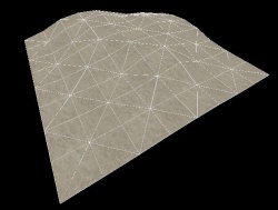
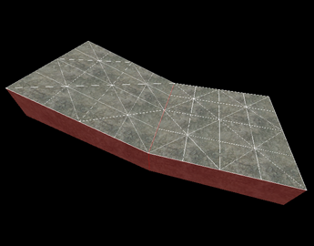
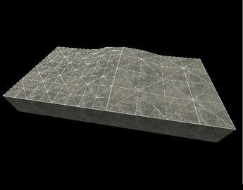
Деформированная поверхность.
Выбирая Texture Application Tool, вызывается диалоговое окно Face Edit Sheet. Вкладка Displacement содержит инструменты для создания и редактирования геометрии деформированных поверхностей. Вкладка Materials содержит инструменты, используемые при редактировании свойств текстур объектов на уровне граней. См. диалог редактирования поверхностей.
Геометрия деформированных поверхностей — это поверхности брашей, преобразованные в треугольную сетку, которую можно искажать как угодно и придавать ей любую форму. Первоначальная функция деформированных поверхностей — создание ландшафта: холмов, долин, углублений, склонов и т. д.
Вкладка Displacement
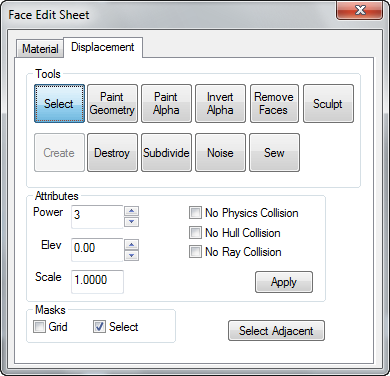
Диалоговое окно Face Edit, используемое для редактирования деформированных поверхностей.
Вкладка Displacement в диалоговом окне Face Edit позволяет создавать и совершать манипуляции с деформированными поверхностями на выбранных гранях браша. Чтобы выбрать грань браша, щёлкните по нему в окне 3D-вида левой кнопкой мыши. Чтобы выделить несколько граней, удерживайте клавишу Ctrl. Также, можно выбрать несколько брашей до выбора инструмента Texture Application.
Инструменты, доступные на вкладке Face Edit Displacements, описаны ниже.
Select
Используется, чтобы выбирать грани брашей и деформированных поверхностей для редактирования. Удерживая Ctrl можно выделить больше граней, а удерживая ⇧ Shift — инвертировать выбранные грани.
Create
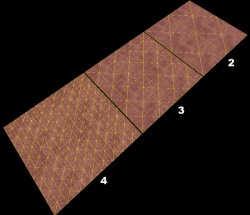
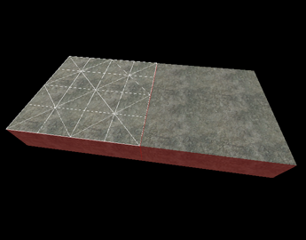
Опция Power — сравнение кол-ва делений.
Создаёт новую деформированную поверхность на выбранной грани браша. Деформация имеет три уровня деления: 2, 3, или 4. Это изображение показывает уровни разрешения деформации.
Разрешения (или power на 2):
- 2 — создаёт 4 деления вдоль каждого края грани ( 2² )
- 3 — создаёт 8 делений вдоль каждого края грани ( 2³ )
- 4 — создаёт 16 делений вдоль каждого края грани ( 2⁴ )
 Примечание:Хотя края грани могут иметь разную длину, число делений на это не влияет.
Destroy
Удаляет выбранные деформированные поверхности, возвращая их в состояние обычных граней.
Paint Geometry
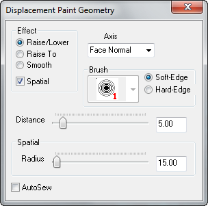
Инструменты рисования деформации.
Открывает панель Displacement Paint Geometry, которая позволяет изменять геометрию выбранных деформаций с помощью инструмента рисования.
Effect
Определяет тип рисования геометрии, который вам нужен:
- Raise/Lower — в пространственном и брашевом режимах рисования увеличивает или уменьшает высоту геометрии. Левой кнопкой мыши геометрия поднимается вдоль текущей оси, правой — опускается. Ползунок Distance задаёт глубину смещения на каждый щелчок мыши.
- Raise to — в пространственном режиме рисования задаёт высоту геометрии относительно высоты, указанной в ползунке Distance в единицах, соответствующих деформированной грани.
- Smooth — в пространственном режиме рисования усредняет позицию геометрии, эффективно сглаживая неровности.
Spatial
Включает пространственный режим рисования. Снятие этого флажка переводит инструменты в режим рисования браша. Пространственное рисование использует трёхмерную сферу, которая определяет геометрию рисунка. Брашевое рисование использует фиксированные вершины браша, влияя на число окружающих вершин относительно его центра.
Axis
Определяет направление оси рисования:
- X, Y, Z — геометрия будет рисоваться только по осям X, Y, или Z, независимо от направления деформации.
- Face Normal — геометрия рисуется относительно определённой оси, заданной конкретной гранью. Выбирать направление рисования можно с помощью Alt+
 на любой грани в окне 3D-вида. Щелчок по грани последовательно переключает направление.
- Subdiv Normal — ось рисования задаётся кривой, сгенерированной командой Subdivide на выбранной грани.
Brush
В режиме браша можно задавать размер изменяемой геометрии. Число на иконке кисти показывает количество охватываемых ею вершин. Например, 3 — действует в радиусе трёх вершин, где вы щёлкнули по деформированной поверхности. Brush не активен, когда выключен режим Spatial.
Soft-Edge/Hard-Edge
Переключатели ослабления рисования в пространственном режиме. В режиме Soft-Edge, эффект искажения геометрии ближе к центру сферы будет выражен сильнее, ослабевая у краёв. В режиме Hard-Edge, вся геометрия будет рисоваться одинаково вне зависимости от позиции в сфере.
Эти элементы управления работают только в режиме Spatial, и отключаются, когда этот режим не активен.
Distance
В режиме Raise/Lower, этот ползунок устанавливает размер рисования геометрии за каждый щелчок мыши с расстоянием в общих единицах. Например, если значение Distance установлено на 5, каждый щелчок левой кнопкой мыши в режиме Raise/Lower будет сдвигать геометрию на 5 единиц.
В режиме Raise To, этот ползунок задаёт высоту смещения геометрии в общих единицах. Например, если значение Distance установлено на 128, каждый щелчок левой кнопкой мыши в режиме Raise/Lower будет сдвигать геометрию на 128 общих единиц от поверхности базовой грани.
В режиме рисования Smooth, чем меньше значение ползунка Distance, тем больше будет сглаживание.
Radius
Задаёт размер рисующей сферы в режиме Spatial. Ползунок Radius работает только при включённом режиме Spatial.
 Совет:Значение ползунка Radius может изменяться динамически, если зажать клавишу Alt и двигать левой кнопкой мыши в окне 3D-вида при активном режиме Spatial.
Autosew
Включение этой опции заставляет  Hammer каждый раз автоматически выполнять команду Сшивание, при выполнении операции рисования выбранной геометрии.
Примечание:Включение Autosew при большом количестве деформированных поверхностей может сильно повлиять на производительность. См. команду сшивание.
 Ошибка:Иногда Hammer путает положение этого флажка. Если во время рисования деформаций у вас возникают проблемы с производительностью, попереключайте его.
Основы создания деформации
Как создавать и рисовать деформированную поверхность:
- С помощью инструмента Block Tool нарисуйте браш, который в дальнейшем будет использован для создания деформированной поверхности.
- Щёлкните по Texture Application, чтобы вызвать диалог Face Edit, и выберите вкладку Displacement.
- В окне 3D-вида выделите сторону браша, щёлкнув по ней левой кнопкой. Удерживайте Ctrl, чтобы добавить или убрать выделенную сторону.
- На вкладке Displacement щёлкните Create. Введите значение плотности деформации от 2 до 4 и нажмите OK.
- На вкладке Displacement выберите инструмент Paint Geometry. Откроется панель Paint Geometry.
- В окне 3D-вида, левая кнопка поднимает выделенную сторону, а правая опускает её. Управляйте размером рисующей сферы с помощью ползунка Radius на панели Paint Geometry.
Paint Alpha
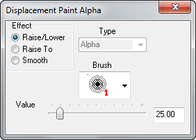
Инструменты рисования вершин деформации.
Откройте панель Displacement Paint Alpha, которая позволит рисовать альфа канал на выбранных деформациях. Альфа канал управляет видимостью двух отдельных текстур на поверхности деформации.
Примечание:Альфа канал влияет только на те деформации, чьи материалы имеют свойства смешивания шейдеров.
Effect
Определяет, какой вид альфа-рисования вам нужен:
- Raise/Lower — увеличивает или уменьшает альфа-значение затронутых вершин.
 увеличивает альфа-значение, уменьшает его. Ползунок Value определяет, насколько быстро будет меняться значение при рисовании.
- Raise to — устанавливает альфа-значение затронутых вершин в соответствии с положением ползунка Value, от 0 до 255.
- Smooth — усредняет альфа-значение затронутых вершин, эффективно сглаживая их в разных вариантах.
Brush
Задаёт размер кисти в режиме альфа-рисования. Число рядом с иконкой кисти показывает её ширину и, соответственно, количество закрашиваемых вершин. Например, 3 влияет на все вершины в радиусе 3-х там, где щелкаете по деформации.
Value
В режиме Raise/Lower этот ползунок задаёт скорость изменения альфа-значений за каждый щелчок по геометрии.
В режиме Raise To этот ползунок задаёт точное альфа-значение для каждой вершины, от 0 до 255.
В режиме Smooth ползунок Value не работает.
Invert Alpha
Инвертирует все данные альфа-канала на выбранных деформациях.
Subdivide
Создаёт гладкую разделённую поверхность из двух или более выбранных деформаций.
Примечание:Одновременное разделение большого числа деформированных поверхностей требует большого объёма вычислений, и может занять много времени.
Noise
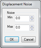
Диалог шума деформации.
Добавляет случайный шум к выбранной деформированной поверхности.
- Значение Min задаёт наибольшее расстояние в единицах, в которых точка на деформации будет двигаться вниз вдоль нормали грани.
- Max задаёт наибольшую дистанцию движения вверх вдоль нормали грани.
- Нажатие OK задаст случайную позицию на деформации где-то между этими двумя значениями.
Sew
Соединяет края двух или более выбранных деформированных поверхностей. Вы можете сшивать их в любом из следующих случаев:
- Любые две деформации, чьи базовые поверхности имеют совместную границу с совпадающими точками.
- Деформации с разным разрешением.
- Деформированная и не деформированные грани браша, имеющие совместную границу.
- Одна деформированная поверхность с другой, имеющей ровно половину ширины от неё (называется T-образным соединением).
Примеры с использованием команды сшивания:
Смежные деформации с общей границей базовых граней.
Деформации с разным разрешением.
Деформация, имеющая общую границу с брашем.
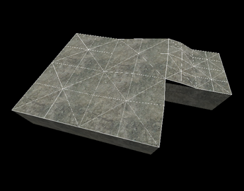
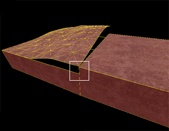
Деформации, имеющие общую границу со средней точкой.
Поверхности не сшиваются, если деформации не имеют совместной границы:
Поверхности, не имеющие общей границы, не могут быть соединены.
Лепка
Откройте панель Displacement Sculpt.
Это уникальный инструмент, т. к. на лету меняет размер во время модификации деформации.
Горячие клавиши
Используйте с перетаскиванием, чтобы увеличивать размер браша, и с перетаскиванием, чтобы уменьшать его.
Ctrl + щелчок работает также, как и правый щелчок инструмента рисования деформации.
⇧ Shift + щелчок старается выровнять область, по которой вы щелкаете.
Alt + Right-click
Настройки
Push и Carve (нажатие и обрезка) — два основных способа редактирования деформаций. Оба они гораздо мощнее оригинального инструмента Displacement.
Существует ряд параметров, имеющихся в обоих инструментах, и работающих одинаково.
- AutoSew — вполне очевидно. Если включён, автоматически сшивает две деформации.
- Offset Mode — здесь два основных смещения: абсолютное и адаптивное. Абсолютное добавляет любое значение к установкам осей X, Y, Z или их комбинации. Адаптивное, в свою очередь, добавляет определённые % значений.
- Offset Distance — применяется только в режиме Absolute Offset. Это расстояние, в единицах, на которое смещаются точки во время редактирования.
- Offset Percent — применяется только в режиме Adaptive Offset. Это процент размера кисти, на который смещаются точки во время редактирования.
- Smoothing — количество сглаживания, применяемого к модифицируемой области.
- Bounds Limit — имеет две установки: Additive и Attenuated. Additive применяет смещение каждый раз, когда вы проводите модификатором по брашу. Attenuated применяет смещение к каждой точке один раз. Весьма полезно.
- Normal Direction — направление смещения. Имеются X, Y, Z, Brush Center, Screen, и Selected. Brush center будет смещать окрашиваемую область в направлении от центра кисти. Screen будет сдвигать окрашиваемую область по направлению к камере или от неё. Selected works — чертит перпендикулярно грани с помощью Alt+.
Настройки Push
- Falloff Position — процент внутренней части кисти, где будет применяться смещение.
- Falloff Final — процент смещения, при котором спад не снижается. Например, если расстояние смещения составляет 10, а окончание спада 90%, то в областях, где будет применён спад, он не снизится более чем на 9.
Настройки Carve
Carve отличается от Push, потому что вместо круга вы получаете редактируемый график. Модифицируя форму графика, вы изменяете форму модифицируемой области. Это крайне ненадёжный инструмент, поэтому идите медленно и плавно.
Пример того, что можно сделать инструментом Carve. Шаблоны дороги такие, какие надо.
Свойства
Различные свойства, которые можно изменять у деформированных поверхностей.
- Power — установка разрешения деформации. Возможные значения 2, 3, и 4.
- Elev — изменяет расстояние деформации от базовой грани.
- Scale — масштабирует «высоту» деформации — расстояние от базовой грани.
- No Physics Collision — отключает столкновения всех физических объектов с деформацией. Полезно для снега, грязи и т. д.
- No Hull Collision — отключает столкновения всех игроков и ботов с деформацией.
- No Ray Collision — отключает столкновение пуль с деформацией. Выстрелы и пули не будут сталкиваться с деформированной поверхностью.
- Apply — фиксирует все изменения значений в Power, Elev, или Scale.
Masks
These options change the way displacement surfaces are displayed when selected in the 3D Views. Enabling the Grid mask disables the drawing of the wireframe displacement grids when selecting displacements. Choosing Select disables the red shading of selected displacements.
See also
Selecting the Texture Application Tool brings up the Face Edit Sheet dialog box. The Displacement tab contains tools to create and edit displacement geometry. The Materials tab contains tools that are used to edit texture properties of objects on a per face level. See Face Edit, Materials.
Displacement geometry are brush surfaces that have been converted to a triangle mesh of faces that can be freely distorted and sculpted into various shapes. The primary function for displacement surfaces is to create terrain -- hills, valleys, trenches, slopes, etc.
Displacement tab
The Face Edit dialog is used for editing displacements.
The Displacement tab in the Face Edit dialog allows you to create and manipulate the displacement surfaces on the selected brush faces. To select a brush face, click on it in the 3D view with the left mouse button. To select multiple faces, hold down the CTRL key while you do this. You can also select multiple brushes before selecting the Texture Application tool.
There are a number of tools available in
Face Edit Displacements tab, described below.
Select
The tool used to select brush and displacement faces for editing. CTRL-click to add faces to the selection, and SHIFT-click a brush to invert the selection of all faces on the brush.
Create
The options for Power - the displacement resolution.
Create a new displacement surface on the selected brush faces. Displacements come in three levels of resolution: 2, 3, or 4. This image shows the levels of displacement resolution.
The resolutions ( or powers of 2):
- 2 - creates 4 divisions along each face edge ( 2^2 )
- 3 - creates 8 divisions along each face edge ( 2^3 )
- 4 - creates 16 divisions along each face edge ( 2^4 )
Примечание: Although each face edge may be a different length, the number of divisions along each face edge is not affected by the length.
Destroy
Delete the selected displacement surfaces, reverting them back to non-displacement faces on the base brush.
Paint Geometry
The displacement painting tools.
Opens the Displacement Paint Geometry panel, which allows you to modify the geometry of the selected displacements using the painting tools.
Effect
Determines what type of geometry painting you wish to do:
- Raise/Lower - In both spatial and brush painting modes, increase or decrease the height of the geometry effected. Left-clicking raises the geometry along the current axis, Right-clicking lowers it. The Distance slider determines how far the geometry moves with each mouse click.
- Raise to - In spatial painting mode, sets the height of the geometry to the height specified in the Distance slider, in world units relative the displacement's base brush face.
- Smooth - In spatial painting mode, averages the position of the geometry, effectively smoothing out variations.
Spatial
Enables spatial painting mode. Turning this flag off puts the tools into brush painting mode. Spatial painting uses a three-dimensional sphere to determine the geometry that is effected by the painting. Brush painting uses a fixed-vertex brush that affects a set number of vertices surrounding the vertex the brush is centered on.
Axis
Determines the axis that what direction faces will move when painted:
- X, Y, Z - Painted geometry will move along the world axis X, Y, or Z only, regardless of the direction of the displacement direction.
- Face Normal - Painted geometry will move along an axis determined by the normal of one specific face. Change the painting direction by using <Alt>+right-click on any face in the 3D view. The normal of the clicked face will become the direction of subsequent painting.
- Subdiv Normal - Painted geometry will move along an axis determined by the curve generated after using the Subdivide command on a set of faces.
Brush
When in brush painting mode, selecting a brush here will use that brush size to determine what geometry is altered when painting. The number next to each brush icon represents how many vertices wide the brush is. For example, a "3" brush will affect all vertices within a 3 vertex radius of where you clicked on a displacement. Brush selection is disabled while in Spatial painting mode.
Soft-Edge/Hard-Edge
Switches the falloff of painting when in spatial editing mode. In Soft-Edge mode, geometry near the center of the painting sphere will be most affected by painting operations, with the effect diminishing towards the edges of the sphere. In Hard-Edge mode, all geometry will be identically affected by painting operations, regardless of their position in the sphere.
These controls only affect Spatial painting mode, and are disabled when Spatial painting is not active.
Distance
When in Raise/Lower mode, this slider sets the amount that geometry will move with each click while painting geometry, as a distance of world units. For example, if the Distance slider is set to "5", each click with the left mouse button while in Raise/Lower painting mode will move the geometry 5 world units.
While in Raise To mode, this slider sets the height that geometry will move to, in world units. For example, if the Distance slider is set to "128", each click with the left mouse button while in Raise/Lower painting mode will move the geometry to exactly 128 world units from the base brush face.
While in Smooth painting mode, the lower the value of the Distance slider, the more smoothing will be applied.
Radius
Sets the size of the painting sphere while in Spatial painting mode. The Radius slide only affects Spatial painting mode, and is disabled when Spatial painting is turned off.
Совет:The Radius slider value can also be dynamically changed by holding down <Alt> and clicking and dragging with the left mouse button in the 3D View, while Spatial painting mode is active.
Autosew
Enabling this option will force Hammer to automatically do a
Sew command after every paint operation on the selected geometry.
Примечание:Enabling Autosew while a large number of displacement surfaces are selected can drastically affect performance. See the Sew command for more information.
Ошибка:Sometimes, Hammer will confuse the state of this checkbox. If you experience performance issues while editing displacements, try toggling this option. Basic Displacement Creation
How to create and paint a displacement surface:
- Create a brush with the Block Tool that will be used a the base for the created displacement surface.
- Click the Texture Application tool to bring up the Face Edit dialog, and select the Displacement tab.
- In the 3D view, left-click on a brush face to select it. <Ctrl>-click to add or remove faces from the current selection.
- Click Create in the Displacement tab. Enter a value from 2 to 4 for the displacement density and click OK.
- Select the Paint Geometry tool on the Displacement tab. The Paint Geometry panel will open.
- In the 3D View, Left-click on a displacement to raise a section, and right-click to lower it. Use the Radius slider in the Paint Geometry panel to control the size of the painting sphere.
Paint Alpha
The displacement vertex alpha painting tools.
Opens the
Displacement Paint Alpha panel, which allows you to paint the alpha channel for the selected displacements. The alpha channel controls the visibility of two separate textures on the displacement surface.
Примечание:Alpha channel values only affect displacements with materials containing the proper blended material shader.
Effect
Determines what type of alpha painting you wish to do:
- Raise/Lower - Increase or decrease the alpha value of the vertices affected. Left-clicking raises the alpha value, Right-clicking lowers it. The Value slider determines how quickly the value will change as you paint.
- Raise to - Sets the alpha value of the affected vertices to the value specified in the Value slider, from 0 to 255.
- Smooth - Averages the alpha value of the affected vertices, effectively smoothing out any variations.
Brush
When in alpha painting mode, selecting a brush here will use that brush size to determine which vertices are altered when painting. The number next to each brush icon represents how many vertices wide the brush is. For example, a "3" brush will affect all vertices within a 3 vertex radius of where you clicked on a displacement.
Value
When in Raise/Lower mode, this slider sets the how quickly the alpha values will change with each click while painting geometry.
While in Raise To mode, this slider sets the exact alpha value that each vertex will be set to, from 0 to 255.
The Value slider has no effect while in Smooth painting mode.
Invert Alpha
Inverts all alpha data on the selected displacements.
Subdivide
Create a smooth subdivision surface out of two or more selected displacement surfaces.
Примечание:Subdividing a large number of displacement surfaces simultaneously requires a lot of computation, and can take a significant amount of time to complete.
Noise
The displacement noise dialog.
Add random noise to the selected displacement surface.
- The Min value sets the greatest distance in units that a point on the displacement will move downward along the face normal.
- Max sets the greatest distance upward along the face normal.
- Clicking OK will randomize the position of the points on the displacement somewhere between these two values.
Sew
Connect the edges of two or more selected displacement surfaces. You can sew displacement surfaces in any of the following circumstances:
- Any two displacements whose base brushes surfaces share a common edge when coincident endpoints.
- Displacements with different resolution settings.
- A displacement surface to a non-displacement brush face, as long as the base face of the displacement shares a common edge.
- A displacement surface to another displacement surface where a shared edge is exactly half the width of the other (called a T-junction).
Examples of circumstances where the Sew command can be used:
Adjacent Displacements with base faces that share an edge.
Displacements with different resolutions.
Displacement with a base face that shares an edge with a brush.
Displacements that share an edge at the exact midpoint.
Surfaces cannot be sewn together if the base faces of the displacements do not share a common edge:
Surfaces that don't share a common edge cannot be connected.
Sculpting
Opens the Displacement Sculpt panel.
This tool is unique as it makes on-the-fly changes to the size when you modify the displacements.
Hotkeys
Use Right-Click and drag to the right to increase the size of the brush, and drag it to the left to decrease the size of the brush.
Ctrl + click works in the same fashion as right click on the Paint Displacement tool.
Shift + click will attempt to even out the area you are clicking over.
Alt + Right-click
Settings
Two major ways of editing displacements, Push, and Carve. Both of these are more powerful than the original Displacement tool.
There are a number of settings that are present on both editing tools, and they have the exact same usages in both tools.
- AutoSew - Fairly self-explanatory. It automatically sews any two displacements together when editing if enabled.
- Offset Mode - There's two major offsets; Absolute, and Adaptive. Absolute adds any value you set to the X,Y,Z axis or any combination thereof. Adaptive, however, adds a certain % value of the brush you modify the displacement with.
- Offset Distance - Only applicable when using the Absolute Offset Mode. This is the distance, in units, in which the point(s) will be moved when they are edited.
- Offset Percent - Only applicable when using the Adaptive Offset Mode. This is the percentage of the size of the brush that the point(s) will be moved when they are edited.
- Smoothing - How much smoothing is added to the modified area.
- Bounds Limit - Has two settings; Additive and Attenuated. Additive applies the offset every time you go over a brush with your modifier. Attenuated applies the offset to each point once. Very useful.
- Normal Direction - Which direction should the offset be applied to. Has X, Y, Z, Brush Center, Screen, and Selected. Brush center will move the brushed area in the direction of where the center of your brush is. Screen will move the brushed area towards the camera, or away from it. Selected works by taking the line perpendicular to the face you Alt + Right-Click on.
Push Settings
- Falloff Position - Percentage of the interior of the brush where the entire offset will be applied.
- Falloff Final - Percentage of the offset of where the fallout will not go below. For example, if offset distance is 10, and falloff final is 90%, the areas where falloff will be applied will not go below 9.
Carve Settings
Carve is different from Push because instead of a circle, you are given an editable graph. By modifying the graph's shape, you can change the shape of the area you modify. This tool is extremely fickle, so go slowly and smoothly.
An example of what the Carve tool can accomplish. Road templates such as this are nice.
Attributes
Different attributes that can be changed for displacement surfaces.
- Power - Sets the resolution of the displacement. Possible values are 2, 3, and 4.
- Elev - Changes the distance of the displacement from the base face.
- Scale - Scales the displacement "height" -- the distance from the base face.
- No Physics Collision - Disables any physics objects colliding with the displacement. Useful for snow, mud, etc.
- No Hull Collision - Disables any player or NPC collisions with the displacement.
- No Ray Collision - Disables raycasts colliding with the displacement. Gunfire and bullets will not collide with the displacement surface.
- Apply - Commits any changes to the Power, Elev, or Scale values.
Masks
These options change the way displacement surfaces are displayed when selected in the 3D Views. Enabling the Grid mask disables the drawing of the wireframe displacement grids when selecting displacements. Choosing Select disables the red shading of selected displacements.
See also


