Blender Modelling Walkthrough/ru
Данная страница содержит информацию, которая частично либо некорректно переведена, или здесь вообще нет перевода.
Кроме того, не забудьте использовать русский
статье об альтернативных языках.
Кроме того, не забудьте использовать русский словарь переводчика.
Эта переведенная страница нуждается в обновлении.
Вы можете помочь, закончив перевод.
Кроме того, не забудьте использовать русский статье об альтернативных языках.
Кроме того, не забудьте использовать русский словарь переводчика.
Это руководство охватывает создание модели в Blender и ее последующий экспорт в Source. Моделью, которую мы делаем, является банка газировки. Чтобы сделать ее, мы будем использовать имеющиеся в Blender инструменты редактирования объектов и наложения текстур.
Это руководство основано на Blender версии 2.48 для Windows, но оно вполне должно соответствовать версии 2.49. Скрипты и инструкции перечисленные в этом руководстве не были проверены на ранних версиях Blender.
Установка
Если вы этого еще не сделали, пожалуйста выполните инструкции изложенные в статье Installing Blender, чтобы убедиться в том, что все сделано должным для завершения этого руководства образом.
В этом руководстве был использован следующий Плагин экспорта dvondrake's Exporter.
Значения клавиш
| Клавиши | |
|---|---|
| Левая кнопка мыши | |
| Средняя кнопка мыши | |
| Правая кнопка мыши | |
| MW | Колесико мыши |
| MWUp | Колесико мыши вверх |
| MWDown | Колесико мыши вниз |
| 9 | 9 на основной клавиатуре |
| Num9 | 9 на цифровой клавиатуре |
Начало работы

Теперь, если вы еще этого не сделали, загрузите Blender. У вас должен быть экран по умолчанию, показанный слева.
Для краткого обзора рабочая область Blender разделена на различные области, называемые окнами просмотра. Каждая область просмотра содержит свой «Тип окна», который можно изменить, щелкнув значок «Тип окна». Кроме того, каждый «Тип окна» имеет заголовок, который можно переместить в верхнюю или нижнюю часть окна или полностью удалить, щелкнув по нему с помощью ![]() . Blender запускается с тремя открытыми по умолчанию окнами просмотра:
. Blender запускается с тремя открытыми по умолчанию окнами просмотра:
- 1. Окно настроек пользователя
- 2. Окно 3D вида
- 3. Окно кнопок
Мы поговорим об этом позже, но пока это все.
Регулировка настроек
Окно пользовательских настроек по умолчанию скрыто, виден только заголовок. Чтобы упростить отслеживание, давайте включим опцию имени вида в окне настроек. Поместите курсор прямо под заголовком «File Add Timeline ...», он должен измениться с указателя на стрелку вверх / вниз. Поместив курсор в виде стрелки вверх / вниз, нажмите ![]() и перетащите курсор вниз примерно до середины трехмерного изображения и отпустите его. Если вкладка «Просмотр и элементы управления» неактивна, щелкните по ней, затем нажмите кнопку «Просмотр имени» (слева от области просмотра) с помощью
и перетащите курсор вниз примерно до середины трехмерного изображения и отпустите его. Если вкладка «Просмотр и элементы управления» неактивна, щелкните по ней, затем нажмите кнопку «Просмотр имени» (слева от области просмотра) с помощью ![]() . Имя позиции теперь должно быть видно в верхней левой части 3D-вида. Когда вы закончите настройку параметров, снова поместите курсор под заголовком «Временная шкала добавления файла ...», а затем перетащите его обратно в верхнюю часть экрана с помощью
. Имя позиции теперь должно быть видно в верхней левой части 3D-вида. Когда вы закончите настройку параметров, снова поместите курсор под заголовком «Временная шкала добавления файла ...», а затем перетащите его обратно в верхнюю часть экрана с помощью ![]() .
.

Создание модели
Для начала сохраните файл изображения ниже где-нибудь на вашем компьютере и запишите его местоположение. Мы будем использовать его позже в этом уроке, чтобы создать скин модели. Для этого урока я сохранил изображение в "c:\Modeling\Blender\SourceSDK\Guide\".

Затем давайте избавимся от света и камеры, а затем удалим куб. Чтобы выбрать и источник света, и камеру, сначала выберите один из двух с помощью ![]() , затем выберите другой, удерживая ⇧ Shift и щелкнув по нему с помощью
, затем выберите другой, удерживая ⇧ Shift и щелкнув по нему с помощью ![]() . Теперь нажмите H, чтобы скрыть их обоих из поля зрения. Вы можете отобразить их позже, нажав ALT H. Теперь выберите куб с помощью
. Теперь нажмите H, чтобы скрыть их обоих из поля зрения. Вы можете отобразить их позже, нажав ALT H. Теперь выберите куб с помощью ![]() и удалите его, нажав X и подтвердив удаление, нажав "Стереть выбранное" с
и удалите его, нажав X и подтвердив удаление, нажав "Стереть выбранное" с ![]() .
.

Добавьте цилиндр, нажав SPACEBAR, затем выбрав "Добавить"> "Сетка"> "Цилиндр" (если вы выбрали неправильный элемент, просто нажмите ESC, чтобы отменить операцию). Когда появится окно подтверждения «Добавить цилиндр», измените количество вершин на 12, затем нажмите «ОК», чтобы создать его. Цилиндр создается на месте "3D курсора" Blender.

Теперь переименуем цилиндр. Выбрав цилиндр, переключитесь на панель кнопок редактирования, нажав F9 (или щелкнув квадрат из четырех точек), а затем замените «Цилиндр» на «BlenderSoda» в полях ME: и OB.

Перемещение объекта и «исходной точки» (центра объекта)
Хотя «центр» цилиндра (маленькая точка выбора) уже должен быть в координатах «0 0 0», он также находится в центре самой геометрии, что нам не нужно. Вместо этого нам нужно, чтобы он находился внизу объекта, для этого нам нужно будет изменить положение меша. Переключитесь на "вид спереди", нажав Num1 (или нажав "View" и выбрав "Front"), и, если цилиндр еще не выбран, сделайте это, щелкнув по нему с помощью ![]() . Чтобы переместить геометрию и оставить центр на месте, перейдите в режим редактирования, нажав Tab ⇆. Убедитесь, что выбран весь цилиндр, нажав A (удалить все / выбрать все), пока все не будет выделено, затем нажмите G, чтобы перейти в режим захвата, Z чтобы ограничить перемещение по оси Z, и 1, чтобы переместить геометрию на 1 единицу вверх.
. Чтобы переместить геометрию и оставить центр на месте, перейдите в режим редактирования, нажав Tab ⇆. Убедитесь, что выбран весь цилиндр, нажав A (удалить все / выбрать все), пока все не будет выделено, затем нажмите G, чтобы перейти в режим захвата, Z чтобы ограничить перемещение по оси Z, и 1, чтобы переместить геометрию на 1 единицу вверх.

Редактирование меша
Теперь, все еще находясь в режиме редактирования сетки, спуститесь на панель инструментов 3D Views и включите окклюзию, нажав кнопку «Окклюзия геометрии фона» (значок куба), затем перейдите в «Режим редактирования лица», нажав кнопку «Грань». (треугольник рядом со значком куба).

Rotate the 3D View so you can see the top of the cylinder by pressing ⇧ Shift and dragging down with the ![]() , you can also rotate the view by Num8. Next, activate brush select by pressing B twice, and then highlight the top faces by clicking them with the
, you can also rotate the view by Num8. Next, activate brush select by pressing B twice, and then highlight the top faces by clicking them with the ![]() (in brush select mode
(in brush select mode ![]() selects,
selects, ![]() deselects). If the paint brush is to big, you can reduce it's size by rolling the MWDown. Now exit brush select mode by clicking the
deselects). If the paint brush is to big, you can reduce it's size by rolling the MWDown. Now exit brush select mode by clicking the ![]() or by pressing Esc. Move the selected faces up by pressing G to grab, then press Z then 1 to bring the selected faces up 1 unit along the Z-axis and then
or by pressing Esc. Move the selected faces up by pressing G to grab, then press Z then 1 to bring the selected faces up 1 unit along the Z-axis and then ![]() to confirm.
to confirm.

Opening the UV/Image Editor
Now we need to unwrap the model, to do this we need to first open the "UV/Image Editor" in a new viewport. To do this we have to "split" the 3D view in half; move the cursor down so its at the bottom of the 3D Views toolbar and it should change into "Up/Down" arrows, when it does press the ![]() and select "Split Area" with the
and select "Split Area" with the ![]() . As you move the cursor around a vertical bar should now be following it, position the vertical bar in the center of the 3D view with the cursor and confirm the split position by clicking the
. As you move the cursor around a vertical bar should now be following it, position the vertical bar in the center of the 3D view with the cursor and confirm the split position by clicking the ![]() . The 3D viewport should now have been split in two.
. The 3D viewport should now have been split in two.

Open the UV/Image Editor in the right viewport by click on the "Window Type" icon with the ![]() , then use the
, then use the ![]() again to select "UV/Image Editor".
again to select "UV/Image Editor".

Marking the Seams

Now we could select all the cylinder's faces and pressing U to unwrap the model right now, but if we do we might get odd looking UVs. This is because Blender doesn't know where to separate the texture. To fix this we need to "mark seems" on the model. Move the cursor back into the 3D view and if you're not still in mesh edit mode for the cylinder, reactivate it by select the cylinder and pressing Tab ⇆. Change to "Edge Select Mode" by holding Ctrl and pressing Tab ⇆, when the "Select Mode" menu pops up, release Ctrl and Tab ⇆, then click on "Edges" with the ![]() .
.
To select the first seem we will be using what is know as "Edge Loop Section". Make sure nothing is already selected by again pressing A, then position the cursor so it lies near the center of one of the edges going around the top of the model. Now, while holding Alt, press the ![]() to select a "ring" of edges going around the top of the model. After selecting the edges, hold Ctrl and press E to bring up the "Edge Specials" menu and click "Mark Seem" with the
to select a "ring" of edges going around the top of the model. After selecting the edges, hold Ctrl and press E to bring up the "Edge Specials" menu and click "Mark Seem" with the ![]() . The top ring of edges should now have an orange color to them indicating a seem. Now select just one of the edges going down the side of the cylinder and again use the "Edge Specials" menu to mark another seem. Rotate the view by holding Ctrl and
. The top ring of edges should now have an orange color to them indicating a seem. Now select just one of the edges going down the side of the cylinder and again use the "Edge Specials" menu to mark another seem. Rotate the view by holding Ctrl and ![]() while the cursor is in the 3d View and dragging the cursor up until you can see the bottom of the cylinder. Now repeat the process you used to select and mark the first seem at the top of the cylinder.
while the cursor is in the 3d View and dragging the cursor up until you can see the bottom of the cylinder. Now repeat the process you used to select and mark the first seem at the top of the cylinder.

Unwrapping the model
We should be able to now unwrap the cylinder. Switch back to "Face Select Mode" (Ctrl Tab ⇆) and press A until all the cylinder's faces are selected. Next, press U to bring up the "UV Calculation" menu and select "Unwrap" with the ![]() . The model's UVs should now show up in the UV/Image Editor viewport.
. The model's UVs should now show up in the UV/Image Editor viewport.

Now let's open the texture to map the UVs onto. In the "UV/Image Editor" viewport, goto the "Image" menu and hold down Ctrl while clicking "Open" with the ![]() , doing this will open the file browser in "preview mode", allowing you to see thumbnails of images before opening them. Goto the location you saved the "RedSoda.png"
file to and use the
, doing this will open the file browser in "preview mode", allowing you to see thumbnails of images before opening them. Goto the location you saved the "RedSoda.png"
file to and use the ![]() to select it. The file name should now appear just under the directory location at the top of the file browser, click on "Open Image" to load the image into the "UV/Image Editor" viewport.
to select it. The file name should now appear just under the directory location at the top of the file browser, click on "Open Image" to load the image into the "UV/Image Editor" viewport.

Mapping the UVs
Now it's time to map the cylinder's UVs onto the image. Select the right circular face by moving the cursor over part of its' geometry and press L to select "linked geometry". The whole circular texture should now be highlighted, activate grab mode by pressing G, and drag the object over the right circle on the image. Repeat this process for the left circular texture dragging it over the left circular image. Try and position the circular textures in the center of the image they're below, then scale them up until they mostly cover the circular parts of the image below them without going outside of the circle parts. Scale them by first selecting the coordinates with L, then press S to enter "Scale Mode". By dragging the cursor away from the object the size should increase, by dragging the cursor towards the object the size should decrease, hold ⇧ Shift to lower the change on scale when moving the cursor. (note: tip, the closer the cursor is to an objects center when activating a transformation, such as Scale or Grab, the greater the influence moving the cursor will have on the transformation).

Once you finish with moving the two circular UV maps into place, press A until nothing is selected, then press B once to enter "Box Select Mode". Drag a selection box over just the top set of coordinates in the box shaped UV with the ![]() to select them. Then press G and Y to limit their movement to the Y axis. Just as you did with the circular cooridinates, try to get this top row of coordinates as close to the top of the red box shape on the image without going off of it.
to select them. Then press G and Y to limit their movement to the Y axis. Just as you did with the circular cooridinates, try to get this top row of coordinates as close to the top of the red box shape on the image without going off of it.

Once you're happy with how the coordinates are situated, choose "Images" then "Save As" from the UV/Image Editor's toolbar. Change the file name to "BlenderSoda.png" (the same name we're using for the model), press ↵ Enter to confirm, and click "Save Image" with the ![]() .
.

You can now see a preview of how the image is being mapped onto your model in the 3D view by clicking the "Draw Type" icon in the header and selecting "Textured".

Adding a material
Change to the "Shading" menu in the buttons window and click the "Materials" icon. Use ![]() to click the up/down arrows icon next to "Add New" and choose "0 Material" (if there's no "0 Material" listed, just click on the "Add New" button itself to create one). Change the name from "Material" to "BlenderSoda".
to click the up/down arrows icon next to "Add New" and choose "0 Material" (if there's no "0 Material" listed, just click on the "Add New" button itself to create one). Change the name from "Material" to "BlenderSoda".

To the far right of the panel should be a tab labeled "Texture", click on the tab next to it labeled "Map Input" and click on the UV button. This will tell Blender to use the models UV coordinates to align the material rather then the material settings.

Adding a texture
Now click on the "Texture Buttons" icon with the ![]() to bring up the texture buttons panel. As you did with the material, change the "TE:" name from "Tex" to "BlenderSoda". Click the bar under "Texture Type" and select "Image", two new button panels should show up.
to bring up the texture buttons panel. As you did with the material, change the "TE:" name from "Tex" to "BlenderSoda". Click the bar under "Texture Type" and select "Image", two new button panels should show up.

Under the panel to the far right labeled "Image", click on the up/down icon next to "Load" and choose the image we saved from the UV/Image Editor earlier, "BlenderSoda.png". Take note of where the texture is being loaded from (you can see the location by clicking the folder icon), we will need to go here later. If all has gone well, we should be ready to export the model.

Exporting the model
- To export an animated model, see Animation in Blender.
For the model to work inside the Source Engine, we have to convert it and the texture it uses into the formats the Source engine uses. You will need an export script installed to continue.
Move the cursor back into the 3D viewport and change to object mode by pressing Tab ⇆. Make sure only the cylinder is selected, then goto file, select "Export", then choose Half-Life 2 (.smd).

An export window should pop up, select "Static Mesh", and change the export file name to "BlenderSoda.smd". Before clicking "Export", take note of where Blender is outputting the file to (in this example the folder is "c:\Modeling\Blender\SourceSDK\Guide\").

After exporting the file, goto the directory Blender used for exporting and copy the "BlenderSoda.smd" file into the games "modelsrc" directory. For this example, I'm copying to the Half-Life 2 Death Match SDK folder:
- C:\Program Files\Steam\steamapps\USERNAME\sourcesdk_content\hl2mp\modelsrc
Compiling the QC file
- Main article: Compiling a model.
In the same folder above were the SMD file ("BlenderSoda.smd") was copied, create a new text document, and open it with notepad. Copy and paste the following inside:
$modelname BlenderSoda.mdl
$cdmaterials "models"
$scale 2
$surfaceprop metal
$staticprop
$body mybody "BlenderSoda.smd"
$sequence idle "BlenderSoda" fps 1
$scale 2 is a conversion between Blender units and Source units. For example, if your model was 3 Blender units tall, a scale of 4 would result in a model that was 12 Hammer Units tall.$surfaceprop metal gives the model a metal collision sound when hit with a projectile or jumped on. This won't work unless the model is assigned a collision mesh. For more on surface properties see this article.After checking over the values used in the QC file, save it into the same folder the SMD is in as "BlenderSoda.qc".
To compile the model, open the command prompt (on Windows XP, "Start > Run... > cmd"). Copy and paste the commands below into the prompt, be sure to replace USERNAME with your actual Steam login name before running the command:
"%sourcesdk%\bin\ep1\bin\studiomdl.exe" -game "c:\program files\steam\steamapps\USERNAME\half-life 2 deathmatch\hl2mp" -notxbox "C:\Program Files\Steam\steamapps\USERNAME\sourcesdk_content\hl2mp\modelsrc\BlenderSoda.qc"
The compiled QC files outputs should have been sent to the folder:
"C:\Program Files\Steam\steamapps\USERNAME\half-life 2 deathmatch\hl2mp\models"
Converting the UV/Image to a VTF
- Main article: Creating a Material.
Now we need to convert the "BlenderSoda.png" file we used to texture our model with into Valve's Texture Format. To do so, refer to the tutorial Creating a Material.
The four important thing to note here are:
- The texture file has the same name as the model.
- The converted texture file is located in the proper folder:
"C:\Program Files\Steam\steamapps\USERNAME\half-life 2 deathmatch\hl2mp\materials\models"
- The texture file has a VMT file ("texturename.vmt") with the same name as the material model in Blender ("BlenderSoda.vmt") and folder location ("hl2mp\materials\models") as the texture file
- The VMT file has the proper values assigned to it:
VertexLitGeneric
{
	$basetexture models/BlenderSoda
}
Testing the model compile
Lastly, after you have converted the model and texture into the proper format, it's time to check and see if everything went according to plan.
- Bring up Steam, go to the tools tab, and open the Source SDK
- Make sure you have the right game engine and game selected in the Source SDK window
- Open the Model Viewer, and with the
 , click on "File" then "Load Model".
 - Using the model browser, locate the file "BlenderSoda", and open it.

Hopefully now you'll be looking at your fully compiled and textured model.
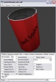
prop in the Model Viewer
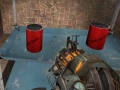
prop in-game


Additional Notes
Image Files:
- The Source Engine requires all image files to have a width and height that are a power of 2 (16, 32, 64, 128, 256, 512, etc). The image used in this tutorial "BlenderSoda.png" had dimensions of 256 x 256. If you want to make your own model texture, make sure it's dimensions follow this convention.
Other Source games
In this tutorial, the model was created for Half-Life 2: Deathmatch, but another Source game can easily be substitued. For the last steps, just use that games model and texture source directories instead of HL2DM's.
|
Eg: For Team Fortress 2 you would use: |
"C:\Program Files\Steam\steamapps\USERNAME\sourcesdk_content\tf\modelsrc
"%sourcesdk%\bin\orangebox\bin\studiomdl.exe" -game "c:\program files\steam\steamapps\USERNAME\team fortress 2\tf" -notxbox "C:\Program Files\Steam\steamapps\USERNAME\sourcesdk_content\tf\modelsrc\BlenderSoda.qc"
"C:\Program Files\Steam\steamapps\USERNAME\team fortress 2\tf\models"C:\Program Files\Steam\steamapps\USERNAME\team fortress 2\tf\materials\models
|
Eg: For Left 4 Dead you would use: |
C:\Program Files\Steam\steamapps\common\left 4 dead\sdk_content\modelsrc
"C:\Program Files\Steam\steamapps\common\left 4 dead\bin\studiomdl.exe" -game "C:\Program Files\Steam\steamapps\common\left 4 dead\left4dead" -notxbox "C:\Program Files\Steam\steamapps\common\left 4 dead\sdk_content\modelsrc\BlenderSoda.qc"
C:\Program Files\Steam\steamapps\common\left 4 dead\left4dead\modelsC:\Program Files\Steam\steamapps\common\left 4 dead\left4dead\materials\models
See also
- Blender
- Modeling props with Blender
- Is Blender 3D Good for Source? - How to Start
- Model Creation Overview